
Error Signal

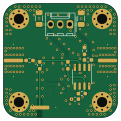
About the Error Signal PCB
Error Signal is an open source PCB design by QSUM-UNB, published on GitHub. It is a 4-layer board measuring 30 × 30 mm, with 25 components from 11 distinct parts.
Other key parts include the REF02HSA+ and OPA2172. By type, the board carries 9 resistors, 8 capacitors, 4 connectors, 2 ICs and 2 inductors.
From the project
PCB designs for a standalone optical frequency-offset locking system.
- © 2026 by K. Shalaby, P. Trottier, T. Reuschel, and B. Barrett - PCB designs licensed under CC BY-NC-SA 4.0
- This repository contains the PCB designs for a standalone optical frequency-offset locking system. All PCB designs were developed in KiCAD. - Files for each circuit component (or tile) are organized into the directory structure described below. - Details about the locking system and its performance can be found in our publication: - K. Shalaby et al, Standalone optical frequency-offset locking electronics for atomic physics, Rev. Sci. Instrum. 97, 033004 (2026). Pre-print…
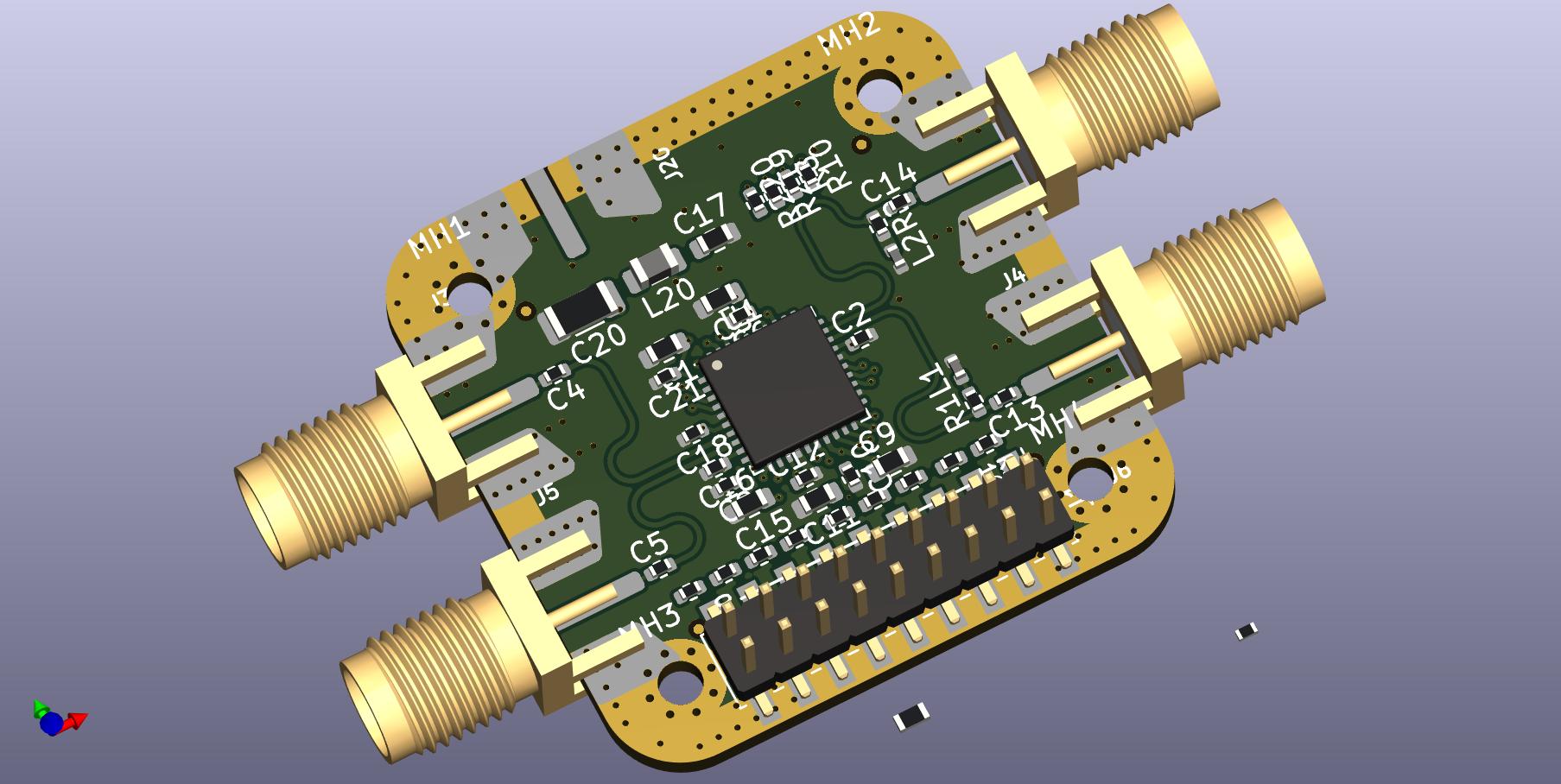
Main components on the Error Signal
Error Signal bill of materials (BOM)
25 components, 11 distinct parts — part numbers from the project's BOM.
| Qty | Part | Footprint | Refs |
|---|---|---|---|
| 1 | REF02HSA+ | SO-8_3.9x4.9mm_P1.27mm | IC1 |
| 1 | OPA2172 | SOIC-8_3.9x4.9mm_P1.27mm | U1 |
| 1 | Input Power | Molex_KK-254_AE-6410-03A_1x03_P2.54mm_Vertical | J1 |
| 3 | 142-1701-626 | SMA-Edge-Generic | J3, J4, J7 |
| 2 | MMZ2012Y202BTD25 | L_0805_2012Metric_Pad1.15x1.40mm_HandSolder | FB1, FB2 |
| 2 | 10NF 10nF | C_0603_1608Metric_Pad1.08x0.95mm_HandSolder | C1, C3 |
| 2 | 1UF 1uF | C_0603_1608Metric_Pad1.08x0.95mm_HandSolder | C2, C4 |
| 2 | 1UF 1uF | C_1206_3216Metric_Pad1.33x1.80mm_HandSolder | C5, C6 |
| 2 | 100NF 100nF | C_0603_1608Metric_Pad1.08x0.95mm_HandSolder | C7, C8 |
| 8 | 1k | R_0603_1608Metric_Pad0.98x0.95mm_HandSolder | R1, R2, R3, R4, R5, R6, R7, R8 |
| 1 | 3k | R_0603_1608Metric_Pad0.98x0.95mm_HandSolder | R9 |
Error Signal design files
The KiCad project lives in the QSUM-UNB/Frequency-Offset-Lock repository on GitHub; these links point at the commit this page was built from.
Error Signal: common questions
How big is the Error Signal PCB?
The Error Signal measures 30 × 30 mm, has 4 copper layers and is 1.6 mm thick.
How many components are on the Error Signal?
25 components, from 11 distinct parts, with part numbers taken from the project's own BOM. The full bill of materials is listed on this page.
Where can I download the Error Signal design files?
From the QSUM-UNB/Frequency-Offset-Lock repository on GitHub, which has the KiCad layout, the schematic and the BOM; the links under Design files point to each one.
Can I use the Error Signal design in my own project?
The repository has no license, so all rights stay with QSUM-UNB. Use it as a reference, and ask the author before reusing the design.
More boards in Frequency-Offset-Lock
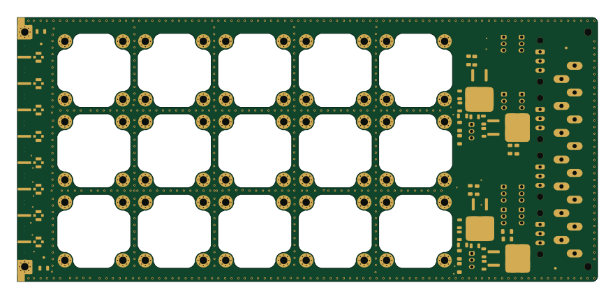
Template 6U220mm PSU+SBC
220 × 100 mm82 parts4LNo license1
Microsemi-MX1DS10P
30 × 30 mm59 parts4LNo license1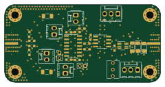
PI Controller
60 × 30 mm55 parts4LNo license1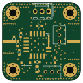
FVC
30 × 30 mm28 parts4LNo license1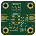
Conditioning
30 × 30 mm20 parts4LNo license1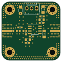
LP Filter
30 × 30 mm17 parts4LNo license1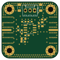
HF Amplifier
30 × 30 mm17 parts4LNo license1