Buzz

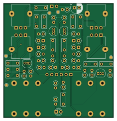
About the Buzz PCB
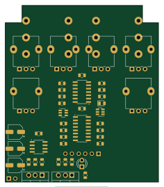
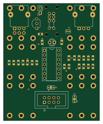
Buzz is an open source PCB design by rabidaudio, published on GitHub. It is a 2-layer board measuring 58.4 × 60.7 mm, with 56 components from 27 distinct parts.
By type, the board carries 23 resistors, 14 capacitors, 5 connectors, 5 diodes, 4 transistors and 1 switch.
From the project
Effects pedals and stomboxes
All components are standard and generic. Gerbers for PCB are in the repo 1 2, as well as case graphics and drill locations which can be ordered on Tayda. Cost of components are around $40 per unit at small quantites.
1. Solder silicon components (BJTs, diodes) except LED. 2. Solder capacitors except electrolytic. 3. Solder resistors. 4. Add leads for power. Keep them long, you can always make them shorter later. 5. Solder jacks, to the back side of the board (the opposite side from the components). Make sure they sit flush with the PCB. 6. Place the potentiometers in the PCB, but don't…
Buzz bill of materials (BOM)
56 components, 27 distinct parts.
| Qty | Part | Footprint | Refs |
|---|---|---|---|
| 4 | Q_NPN | TO-92_Inline | Q1, Q2, Q3, Q4 |
| 1 | AudioJack_IN | Jack_6.35mm_Neutrik_NMJ6HCD3_Horizontal | J1 |
| 1 | AudioJack_OUT | Jack_6.35mm_Neutrik_NMJ6HCD3_Horizontal | J2 |
| 1 | Jack-DC | PinSocket_1x02_P2.54mm_Vertical | J3 |
| 1 | MAIN_BIC | PinSocket_1x06_P2.54mm_Vertical | J4 |
| 1 | SWITCH_BIC | PinSocket_1x06_P2.54mm_Vertical | J5 |
| 1 | R_SUSTAIN-A100K | Potentiometer_Alpha_RD901F-40-00D_Single_Vertical | RV1 |
| 1 | R_MID-A100K | Potentiometer_Alpha_RD901F-40-00D_Single_Vertical | RV2 |
| 1 | R_TONE-B100K | Potentiometer_Alpha_RD901F-40-00D_Single_Vertical | RV3 |
| 1 | R_VOL-A100K | Potentiometer_Alpha_RD901F-40-00D_Single_Vertical | RV4 |
| 1 | SW_3PDT_x3 | Stompbox Switch | SW1 |
| 4 | D | D_A-405_P2.54mm_Vertical_KathodeUp | D1, D2, D3, D4 |
| 1 | LED | LED_D3.0mm | D5 |
| 7 | 100n | C | C1, C3, C4, C5, C7, C8, C13 |
| 3 | 470p | C | C2, C6, C9 |
| 2 | 10n | C | C10, C11 |
| 1 | 1u | C | C12 |
| 1 | 10u | CP_Radial_D6.3mm_P2.50mm | C14 |
| 2 | 33k | R | R1, R17 |
| 4 | 100k | R | R2, R8, R13, R21 |
Show 7 more
| Qty | Part | Footprint | Refs |
|---|---|---|---|
| 4 | 470k | R | R3, R9, R14, R20 |
| 3 | 10k | R | R4, R18, R22 |
| 3 | 100 | R | R5, R11, R16 |
| 2 | 1K | R | R6, R19 |
| 2 | 8.2k | R | R7, R12 |
| 2 | 18k | R | R10, R15 |
| 1 | 3.3k | R | R23 |
Buzz design files
The KiCad project lives in the rabidaudio/effects repository on GitHub; these links point at the commit this page was built from.
- Layoutdist/buzz/buzz.kicad_pcb
- Schematicdist/buzz/buzz.kicad_sch
Buzz: common questions
How big is the Buzz PCB?
The Buzz measures 58.4 × 60.7 mm, has 2 copper layers and is 1.6 mm thick.
How many components are on the Buzz?
56 components, from 27 distinct parts. The full bill of materials is listed on this page.
Where can I download the Buzz design files?
From the rabidaudio/effects repository on GitHub, which has the KiCad layout and the schematic; the links under Design files point to each one.
Can I use the Buzz design in my own project?
The repository has no license, so all rights stay with rabidaudio. Use it as a reference, and ask the author before reusing the design.