
HKTV13RGB

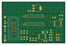
About the HKTV13RGB PCB
HKTV13RGB is an open source PCB design by RetroLoom, published on GitHub under the CERN-OHL-S-2.0 license. It is a 2-layer board measuring 55.9 × 37.2 mm, with 32 components from 18 distinct parts.
Other key parts include the THS7376IPWR, TS5V330CPWR and AMS1117-5.0. By type, the board carries 17 resistors, 7 capacitors, 3 ICs, 3 connectors, 1 jumper and 1 diode.
It belongs with the retro computing designs in this gallery.
From the project
Open-hardware RGB mod for the Emerson HKTV13 "Hello Kitty" CRT TV — an interposer board that injects switchable external RGB while preserving the original OSD.
An open-hardware RGB injection board that adds clean, switchable RGB input to the Emerson HKTV13 Hello Kitty CRT television. The module is an interposer that sits between the TV's neck board and main board, in line with the existing 7-pin OSD link. It either passes the original OSD signals straight through, or pulls them out and injects external RGB in their place — letting you feed RGB from a retro console, scaler, or other source while keeping the set's original on-screen display (OSD) fully usable.
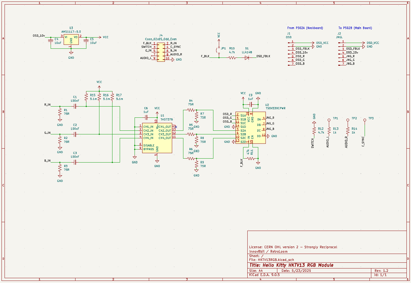
Main components on the HKTV13RGB
HKTV13RGB bill of materials (BOM)
32 components, 18 distinct parts.
| Qty | Part | Footprint | Refs |
|---|---|---|---|
| 1 | THS7376IPWR THS7376 | TSSOP-14_4.4x5mm_P0.65mm | U1 |
| 1 | TS5V330CPWR | TSSOP-16_4.4x5mm_P0.65mm | U2 |
| 1 | AMS1117-5.0 | SOT-223-3_TabPin2 | U3 |
| 1 | OSD | PinHeader_1x07_P2.54mm_Vertical | J1 |
| 1 | JNGL | PinHeader_1x07_P2.54mm_Vertical | J2 |
| 1 | Conn_02x05_Odd_Even | IDC-Header_2x05_P2.54mm_Vertical | J4 |
| 1 | FB - VCC | SolderJumper-2_P1.3mm_Open_RoundedPad1.0x1.5mm | JP1 |
| 1 | LL4148 | D_MiniMELF | D1 |
| 3 | CL21B104KBCNFNC 100nF | C_0805_2012Metric_Pad1.18x1.45mm_HandSolder | C1, C2, C3 |
| 2 | CL21B104KBCNFNC 10uF | C_0805_2012Metric_Pad1.18x1.45mm_HandSolder | C4, C5 |
| 2 | CL21B104KBCNFNC 1uF | C_0805_2012Metric_Pad1.18x1.45mm_HandSolder | C6, C9 |
| 3 | 75R | R_0805_2012Metric_Pad1.20x1.40mm_HandSolder | R1, R2, R3 |
| 3 | RMCF0805FT1K00 75R | R_0805_2012Metric_Pad1.20x1.40mm_HandSolder | R4, R5, R6 |
| 3 | RMCF0805FT150R 75R | R_0805_2012Metric_Pad1.20x1.40mm_HandSolder | R7, R8, R9 |
| 2 | RMCF0805FT150R 4.7k | R_0805_2012Metric_Pad1.20x1.40mm_HandSolder | R10, R12 |
| 1 | RMCF0805FT150R 47k | R_0805_2012Metric_Pad1.20x1.40mm_HandSolder | R11 |
| 2 | RMCF0805FT150R 1k | R_0805_2012Metric_Pad1.20x1.40mm_HandSolder | R13, R14 |
| 3 | 5.1m | R_0805_2012Metric_Pad1.20x1.40mm_HandSolder | R15, R16, R17 |
HKTV13RGB design files
The KiCad project lives in the RetroLoom/HKTV13RGB repository on GitHub; these links point at the commit this page was built from.
- LayoutKiCad/HKTV13RGB.kicad_pcb
- SchematicKiCad/HKTV13RGB.kicad_sch
HKTV13RGB: common questions
How big is the HKTV13RGB PCB?
The HKTV13RGB measures 55.9 × 37.2 mm, has 2 copper layers and is 1.6 mm thick.
How many components are on the HKTV13RGB?
32 components, from 18 distinct parts. The full bill of materials is listed on this page.
Where can I download the HKTV13RGB design files?
From the RetroLoom/HKTV13RGB repository on GitHub, which has the KiCad layout and the schematic; the links under Design files point to each one.
Can I use the HKTV13RGB design in my own project?
Yes, under the terms of its CERN-OHL-S-2.0 license, which RetroLoom chose for the repository.
Similar boards
Expansion Card Retrofit
FrameworkComputer
24 × 27.3 mm5 parts2LCC-BY-4.01.1k
Videoslotadapter
hoglet67
152 × 57.6 mm13 parts2LGPL-3.01.0k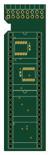
Amiga External
21.9 × 76.7 mm6 parts2LGPL-3.01.0k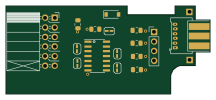
Buffer
53.9 × 23.2 mm13 parts2LGPL-3.01.0k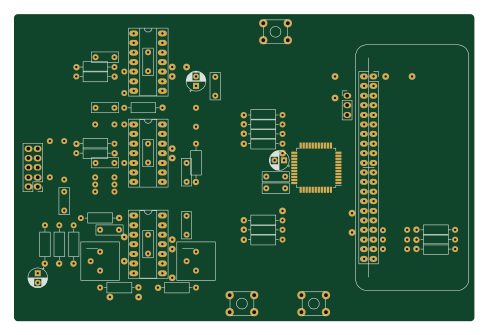
X1
121.9 × 81.3 mm51 parts2LGPL-3.01.0k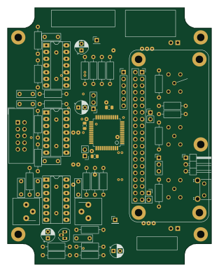
Rgb to hdmi
77 × 97 mm67 parts2LGPL-3.01.0k