
Signalization by fireplace

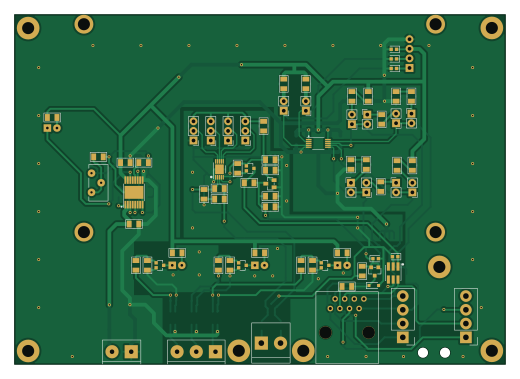
About the Signalization by fireplace PCB
Signalization by fireplace is an open source PCB design by RomLab, published on GitHub. It is a 2-layer board measuring 129.8 × 92.5 mm, with 104 components from 46 distinct parts.
Other key parts include the PCA9615, AP2210N-3.3TRG1, MAX31850K and TPS26600. By type, the board carries 37 resistors, 21 connectors, 20 diodes, 15 capacitors, 5 transistors and 4 ICs.
It belongs with the iot & wireless designs in this gallery.
From the project
PCB for underfloor heating system
There are here schematics, PCBs, 3D views and Gerber data for devices in underfloor heating system. There are two types folders with version KiCAD 5 and KiCAD 7. The libraries are here.
More information at https://github.com/RomLab/system-for-underfloor-heating-v2.0
Main components on the Signalization by fireplace
Signalization by fireplace bill of materials (BOM)
104 components, 46 distinct parts.
| Qty | Part | Footprint | Refs |
|---|---|---|---|
| 1 | PCA9615 NXP Semiconductors | tssop_10 | U1 |
| 1 | AP2210N-3.3TRG1 | sot_23_3 | U2 |
| 1 | MAX31850K Maxim integrated | tdfn_10_ep | U3 |
| 1 | TPS26600 Texas Instruments | htssop_16_6.6mm×5.1mm | U4 |
| 4 | BSS138P | sot_323 | Q1, Q2, Q3, Q4 |
| 1 | YJL3415A | sot_23 | Q6 |
| 2 | 2x1x4_idc_lsa | 1x4_idc_lsa_connector_general | J1, J4 |
| 1 | EBBA-03-C-SS-BU | EBBA-03-C-SS-BU | J2 |
| 1 | 54601-908WPLF | 54601-908WPLF | J3 |
| 1 | DG390-5.0 | DG390-5.0-02P-12-00A(H) | J5 |
| 1 | EBBA-02-C-SS-BU | EBBA-02-C-SS-BU | J6 |
| 1 | DS1023-1-4S21 | 1x4_pin_socket_2.54mm_vertical_8.5mm | P1 |
| 10 | DS1021-1-2SF11-B | 1x2_pin_header_2.54mm_vertical | P2, P3, P4, P5, P6, P7, P8, P9 +2 |
| 4 | DS1021-1-3SF11-B | 1x3_pin_header_2.54mm_vertical | P12, P13, P14, P15 |
| 8 | UCLAMP0501H.TCT | sod_523 | D1, D2, D3, D8, D9, D10, D14, D15 |
| 4 | DS9503_us | tsoc_6 | D4, D5, D6, D12 |
| 1 | SMDA05CDR2G | soic_8_3.9mmx4.9mm | D7 |
| 1 | ESD3B5V0WS | sod_323 | D11 |
| 1 | OSR5PAA6A1A | led_d10mm_2.54mm | D13 |
| 1 | OSO5PAA6A1A | led_d10mm_2.54mm | D16 |
Show 26 more
| Qty | Part | Footprint | Refs |
|---|---|---|---|
| 1 | ESD16VHYFHT116 | sot_23 | D17 |
| 1 | OSB5SAA6A1A | led_d10mm_2.54mm | D18 |
| 1 | LL-503VC1E-4C | led_d5mm_2.54mm | D20 |
| 1 | SMCJ5.0CA-13-F | smc | D22 |
| 2 | BLM31KN471BH1L | ferrite_bead_1206 | L1, L2 |
| 6 | 1uF | c_1206 | C1, C4, C5, C12, C13, C15 |
| 5 | 100nF | c_1206 | C2, C3, C6, C10, C11 |
| 2 | NC | c_1206 | C7, C9 |
| 1 | 10nF | c_1206 | C8 |
| 1 | 1.2nF | c_1206 | C14 |
| 5 | 10R/0.5W | r_1206 | R1, R2, R3, R4, R37 |
| 5 | 4k7 | r_1206 | R5, R6, R27, R28, R31 |
| 3 | 10k | r_1206 | R7, R14, R21 |
| 2 | 130R | r_1206 | R8, R15 |
| 4 | 210R | r_1206 | R9, R13, R16, R20 |
| 4 | 390R | r_1206 | R10, R12, R17, R19 |
| 2 | 100R/120R | r_1206 | R11, R18 |
| 1 | 100R | r_1206 | R22 |
| 2 | 100k | r_1206 | R23, R38 |
| 1 | 3k16 | r_1206 | R24 |
| 1 | 30k | r_1206 | R25 |
| 1 | 200R | r_1206 | R26 |
| 1 | 200k Vishay | T93YB | R29 |
| 1 | 5k36 | r_1206 | R30 |
| 1 | 470R | r_1206 | R32 |
| 3 | 1k | r_1206 | R33, R34, R35 |
Signalization by fireplace design files
The KiCad project lives in the RomLab/pcb-system-for-underfloor-heating-v2.0 repository on GitHub; these links point at the commit this page was built from.
Signalization by fireplace: common questions
How big is the Signalization by fireplace PCB?
The Signalization by fireplace measures 129.8 × 92.5 mm, has 2 copper layers and is 1.6 mm thick.
How many components are on the Signalization by fireplace?
104 components, from 46 distinct parts. The full bill of materials is listed on this page.
Where can I download the Signalization by fireplace design files?
From the RomLab/pcb-system-for-underfloor-heating-v2.0 repository on GitHub, which has the KiCad layout and the schematic; the links under Design files point to each one.
Can I use the Signalization by fireplace design in my own project?
The repository has no license, so all rights stay with RomLab. Use it as a reference, and ask the author before reusing the design.
More boards in pcb-system-for-underfloor-heating-v2.0
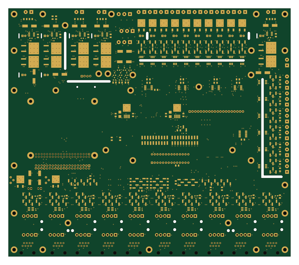 Raspberry Pi
Central control unit
255.9 × 224.5 mm735 parts4LNo license1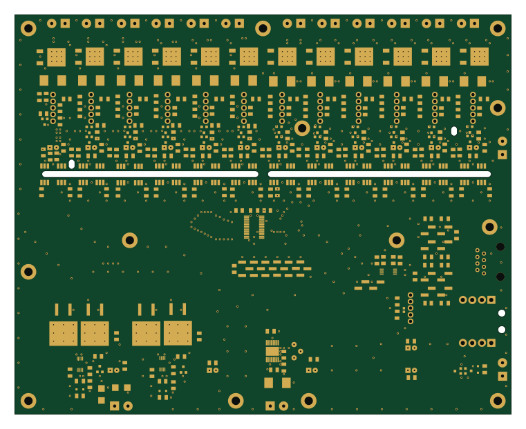
Zone controller
190 × 153.2 mm422 parts2LNo license1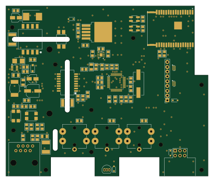 ESP32
ESP32Wall mounted room temperature sensor
107 × 90 mm153 parts2LNo license1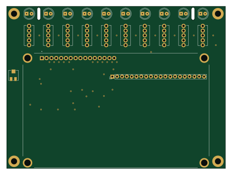
Switches with lcd display
115 × 85 mm76 parts2LNo license1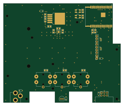 ESP32
ESP32Wall mounted room temperature sensor - Wifi
107 × 90 mm50 parts2LNo license1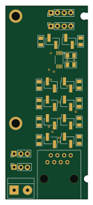
Testing board
31.1 × 73 mm37 parts2LNo license1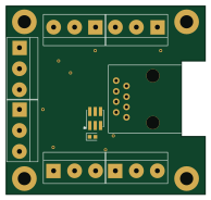
Hub 1-Wire bus
48.3 × 45.7 mm20 parts2LNo license1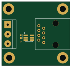
Connection connector 1-Wire bus
36.2 × 33.7 mm10 parts2LNo license1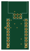
USB to UART converter with module
23.5 × 41.9 mm9 parts2LNo license1
Similar boards

RPi RM0 WiFi/Bluetooth Module
schlae
11.1 × 14 mm76 parts6LNo license1.0k
L0 IMU MPU9250
Luos-io
20.3 × 15.2 mm7 parts2LMIT547
L0 USBA
20.3 × 15.3 mm19 parts2LMIT547
L0 Controller motor
20.3 × 15.3 mm11 parts2LMIT547
L0 Dynamixel
20.3 × 15.2 mm15 parts2LMIT547
L0 stepper driver
20.3 × 15.2 mm18 parts2LMIT547