RG Led ring

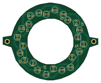
About the RG Led ring PCB
RG Led ring is an open source PCB design by RudgeLab, published on GitHub under the MIT license. It is a 2-layer board measuring 83.8 × 68.6 mm, with 30 components from 2 distinct parts.
By type, the board carries 24 diodes and 6 connectors.
From the project
Code and teaching materials for UC/BackyardBrains raspberry pi "macro" scope.
Hardware design files, code and teaching materials for a low cost and open source fluorescent image registration station.
FluoPi is composed of a blue-light transilluminator, an amber acrylic filter and a raspberry camera contained in a black acrylic mainframe. All the hardware is controlled with a Raspberry pi small computer. With this equipment you are able to:
RG Led ring bill of materials (BOM)
30 components, 2 distinct parts.
| Qty | Part | Footprint | Refs |
|---|---|---|---|
| 6 | Conn_01x01_Female | PinHeader_1x01_P2.54mm_Vertical | J1, J2, J3, J4, J5, J6 |
| 24 | LED | LED_D5.0mm_FlatTop | D1, D2, D3, D4, D5, D6, D7, D8 +16 |
RG Led ring design files
The KiCad project lives in the RudgeLab/FluoPi repository on GitHub; these links point at the commit this page was built from.
RG Led ring: common questions
How big is the RG Led ring PCB?
The RG Led ring measures 83.8 × 68.6 mm, has 2 copper layers and is 1.6 mm thick.
How many components are on the RG Led ring?
30 components, from 2 distinct parts. The full bill of materials is listed on this page.
Where can I download the RG Led ring design files?
From the RudgeLab/FluoPi repository on GitHub, which has the KiCad layout; the links under Design files point to each one.
Can I use the RG Led ring design in my own project?
Yes, under the terms of its MIT license, which RudgeLab chose for the repository.