
SwitchedPhaseShift

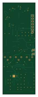
About the SwitchedPhaseShift PCB
SwitchedPhaseShift is an open source PCB design by Saatvik-Aggarwal, published on GitHub under the MIT license. It is a 4-layer board measuring 30 × 85 mm, with 80 components from 27 distinct parts.
Other key parts include the YSGM556006, AMS1117, SBB5089Z, ADL5375-15ACPZ-WP and TLV2372. By type, the board carries 30 capacitors, 17 connectors, 14 ICs, 10 resistors, 2 test points and 2 inductors.
It belongs with the iot & wireless designs in this gallery.
From the project
Simulation and design of a phased array for wireless power transmission
Main components on the SwitchedPhaseShift
SwitchedPhaseShift bill of materials (BOM)
80 components, 27 distinct parts.
| Qty | Part | Footprint | Refs |
|---|---|---|---|
| 1 | YSGM556006 | Innotion9070 | U1 |
| 2 | AMS1117 | SOT-223-3_TabPin2 | U2, U10 |
| 2 | SBB5089Z | SOT_SBB5089Z_QOR | U3, U15 |
| 5 | ~ | SKY13699-21 | U4, U5, U6, U13, U14 |
| 1 | ~ | WilkinsonPowerDivider | U7 |
| 1 | ~ | T_Splitter | U8 |
| 1 | ADL5375-15ACPZ-WP | LFCSP-24-1EP_4x4mm_P0.5mm_EP2.3x2.3mm_ThermalVias | U9 |
| 1 | TLV2372 | SOIC-8_3.9x4.9mm_P1.27mm | U11 |
| 16 | Conn_Coaxial | U.FL_Hirose_U.FL-R-SMT-1_Vertical | J1, J3, J4, J5, J6, J7, J8, J9 +8 |
| 1 | Conn_01x07_Pin | PinSocket_1x07_P2.54mm_Vertical | J2 |
| 1 | Antenna | AperturePatch | AE3 |
| 1 | Jumper_2_Open | SolderJumper-2_P1.3mm_Open_RoundedPad1.0x1.5mm | JP1 |
| 3 | 25k | Potentiometer_Bourns_3386X_Horizontal | RV1, RV2, RV3 |
| 2 | TestPoint | PinHeader_1x01_P2.54mm_Vertical | TP1, TP2 |
| 2 | 82n | L_0402_1005Metric_Pad0.77x0.64mm_HandSolder | L1, L2 |
| 6 | 1u | C_0603_1608Metric_Pad1.08x0.95mm_HandSolder | C1, C2, C4, C14, C15, C27 |
| 4 | 10u | C_0603_1608Metric_Pad1.08x0.95mm_HandSolder | C3, C13, C17, C18 |
| 10 | 8.2p | C_0201_0603Metric_Pad0.64x0.40mm_HandSolder | C5, C6, C9, C12, C19, C21, C26, C28 +2 |
| 4 | 1n | C_0603_1608Metric_Pad1.08x0.95mm_HandSolder | C7, C10, C16, C20 |
| 2 | 68p | C_0201_0603Metric_Pad0.64x0.40mm_HandSolder | C8, C11 |
Show 7 more
| Qty | Part | Footprint | Refs |
|---|---|---|---|
| 2 | 0.1uF | C_0603_1608Metric_Pad1.08x0.95mm_HandSolder | C22, C23 |
| 2 | 100pF | C_0603_1608Metric_Pad1.08x0.95mm_HandSolder | C24, C25 |
| 1 | 30k | R_0603_1608Metric_Pad0.98x0.95mm_HandSolder | R1 |
| 2 | 10k | R_0603_1608Metric_Pad0.98x0.95mm_HandSolder | R2, R3 |
| 1 | 2k | R_0603_1608Metric_Pad0.98x0.95mm_HandSolder | R4 |
| 2 | 50 | R_0201_0603Metric_Pad0.64x0.40mm_HandSolder | R5, R6 |
| 4 | 100k | R_0603_1608Metric_Pad0.98x0.95mm_HandSolder | R7, R8, R9, R10 |
SwitchedPhaseShift design files
The KiCad project lives in the Saatvik-Aggarwal/phased-array repository on GitHub; these links point at the commit this page was built from.
SwitchedPhaseShift: common questions
How big is the SwitchedPhaseShift PCB?
The SwitchedPhaseShift measures 30 × 85 mm, has 4 copper layers and is 1.5422 mm thick.
How many components are on the SwitchedPhaseShift?
80 components, from 27 distinct parts. The full bill of materials is listed on this page.
Where can I download the SwitchedPhaseShift design files?
From the Saatvik-Aggarwal/phased-array repository on GitHub, which has the KiCad layout and the schematic; the links under Design files point to each one.
Can I use the SwitchedPhaseShift design in my own project?
Yes, under the terms of its MIT license, which Saatvik-Aggarwal chose for the repository.
More boards in phased-array

Similar boards
EinkPDA screen
TalismanDesign
95 × 54 mm27 parts2LApache-2.02.0k
RPi RM0 WiFi/Bluetooth Module
schlae
11.1 × 14 mm76 parts6LNo license1.0k
Breakout board
Luos-io
26.7 × 27.9 mm29 parts2LMIT547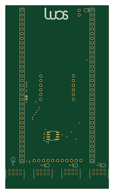
Stm32f0 disco Luos shield
55.9 × 99.1 mm26 parts2LMIT547
L0 USB
20.3 × 15.3 mm19 parts2LMIT547
L0 USBA
20.3 × 15.3 mm19 parts2LMIT547