
Kicad project4 On delay timer

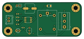
About the Kicad project4 On delay timer PCB
Kicad project4 On delay timer is an open source PCB design by Shivasailanathan-helps, published on GitHub. It is a 2-layer board measuring 69.2 × 30.5 mm, with 14 components from 13 distinct parts.
Other key parts include the NE555D. By type, the board carries 4 resistors, 2 connectors, 2 diodes, 2 capacitors, 1 IC and 1 transistor.
From the project
This Project gives a On-Delay Timer 2 layer PCB in KiCad using an NE555 timer in monostable mode to process low-voltage DC signals and create a designated time delay. The circuit uses a transistor to safely drive an relay for switching high-power AC/DC loads, protected by a flyback diode against spikes, with LED for visual timing status.
Galvanic Load Switching: Onboard SPDT relay (K1) coupled to a 3-pin high-voltage screw terminal block (J2: NC, C, NO) for total electrical isolation between control circuitry and external AC/DC loads.
Visual Status Indication: Through-Hole (THT) 5mm dome LED (D1) with a 330ohm resistor with series current-limiting resistor (R2) for clear, wide-angle visual timing status. Dual-Layer Copper Pour Strategy: Continuous Bottom Copper (B.Cu) Ground (GND) plane for low-impedance current return paths and noise immunity, alongside a Top Copper (F.Cu) +5V power zone for low-resistance power…
Main components on the Kicad project4 On delay timer
Kicad project4 On delay timer bill of materials (BOM)
14 components, 13 distinct parts.
| Qty | Part | Footprint | Refs |
|---|---|---|---|
| 1 | NE555D | SOIC-8_3.9x4.9mm_P1.27mm | U1 |
| 1 | BC547 | TO-92_Inline_Wide | Q1 |
| 1 | Pins | JST_XH_B2B-XH-A_1x02_P2.50mm_Vertical | J1 |
| 1 | AC Connector | TerminalBlock_Phoenix_MKDS-1,5-3-5.08_1x03_P5.08mm_Horizontal | J2 |
| 1 | G5LE-1 | Relay_SPDT_Omron-G5LE-1 | K1 |
| 1 | SW_Push | PinHeader_1x02_P2.54mm_Vertical | SW1 |
| 1 | LED | LED_D3.0mm_Clear | D1 |
| 1 | D_Small | D_1206_3216Metric | D2 |
| 1 | 10uF/16V | C_0603_1608Metric | C1 |
| 1 | 0.01uF | C_Elec_8x10.2 | C2 |
| 1 | 100K | R_0603_1608Metric | R1 |
| 2 | 330E | R_0603_1608Metric | R2, R4 |
| 1 | 10K | R_0603_1608Metric | R3 |
Kicad project4 On delay timer design files
The KiCad project lives in the Shivasailanathan-helps/Kicad_project4_On-delay-timer repository on GitHub; these links point at the commit this page was built from.
Kicad project4 On delay timer: common questions
How big is the Kicad project4 On delay timer PCB?
The Kicad project4 On delay timer measures 69.2 × 30.5 mm, has 2 copper layers and is 1.6 mm thick.
How many components are on the Kicad project4 On delay timer?
14 components, from 13 distinct parts. The full bill of materials is listed on this page.
Where can I download the Kicad project4 On delay timer design files?
From the Shivasailanathan-helps/Kicad_project4_On-delay-timer repository on GitHub, which has the KiCad layout and the schematic; the links under Design files point to each one.
Can I use the Kicad project4 On delay timer design in my own project?
The repository has no license, so all rights stay with Shivasailanathan-helps. Use it as a reference, and ask the author before reusing the design.