
Decoder V2

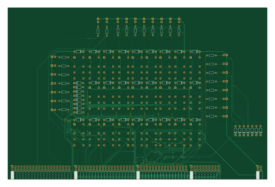
About the Decoder V2 PCB
Decoder V2 is an open source PCB design by Syntaxer04, published on GitHub under the GPL-3.0 license. It is a 2-layer board measuring 219.8 × 145.4 mm, with 122 components from 8 distinct parts.
By type, the board carries 66 diodes, 26 relays, 25 resistors and 5 connectors.
From the project
8-Bit Relay Computer inspired by Harry Porter and DipDot
Decoder V2 bill of materials (BOM)
122 components, 8 distinct parts.
| Qty | Part | Footprint | Refs |
|---|---|---|---|
| 2 | Conn_02x20_Counter_Clockwise | PinSocket_2x20_P2.54mm_Horizontal | J1, J58 |
| 1 | Conn_02x17_Counter_Clockwise | PinSocket_2x17_P2.54mm_Horizontal | J57 |
| 1 | Conn_02x10_Counter_Clockwise | PinSocket_2x10_P2.54mm_Horizontal | J59 |
| 1 | Conn_02x02_Counter_Clockwise | PinSocket_2x02_P2.54mm_Horizontal | J61 |
| 26 | HK19F-DCxxV-SHC | Relay_DPDT_Finder_30.22 ohne SilkS | K1, K2, K3, K4, K5, K8, K9, K10 +18 |
| 41 | 1N914 | D_DO-35_SOD27_P7.62mm_Horizontal | D1, D2, D3, D4, D5, D6, D7, D8 +33 |
| 25 | LED | LED_D5.0mm ohne SilkS | D35, D36, D37, D38, D39, D40, D41, D42 +17 |
| 25 | R | R_Axial_DIN0204_L3.6mm_D1.6mm_P7.62mm_Horizontal | R1, R2, R3, R4, R5, R6, R7, R8 +17 |
Decoder V2 design files
The KiCad project lives in the Syntaxer04/RC1Computer repository on GitHub; these links point at the commit this page was built from.
Decoder V2: common questions
How big is the Decoder V2 PCB?
The Decoder V2 measures 219.8 × 145.4 mm, has 2 copper layers and is 1.6 mm thick.
How many components are on the Decoder V2?
122 components, from 8 distinct parts. The full bill of materials is listed on this page.
Where can I download the Decoder V2 design files?
From the Syntaxer04/RC1Computer repository on GitHub, which has the KiCad layout and the schematic; the links under Design files point to each one.
Can I use the Decoder V2 design in my own project?
Yes, under the terms of its GPL-3.0 license, which Syntaxer04 chose for the repository.
More boards in RC1Computer
Cond.memory
253.4 × 291.8 mm397 parts2LGPL-3.04
ALU V2 v2 - Logik
172.5 × 226.3 mm172 parts2LGPL-3.04
Controller V2
231.2 × 156.8 mm169 parts2LGPL-3.04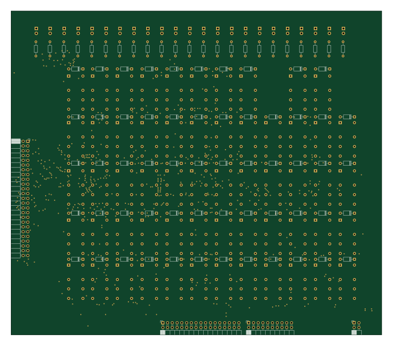
Sequencer
197.8 × 172.8 mm166 parts2LGPL-3.04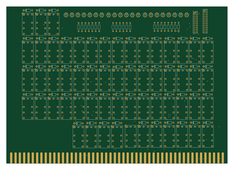
Fulladder
202.5 × 144.2 mm162 parts2LGPL-3.04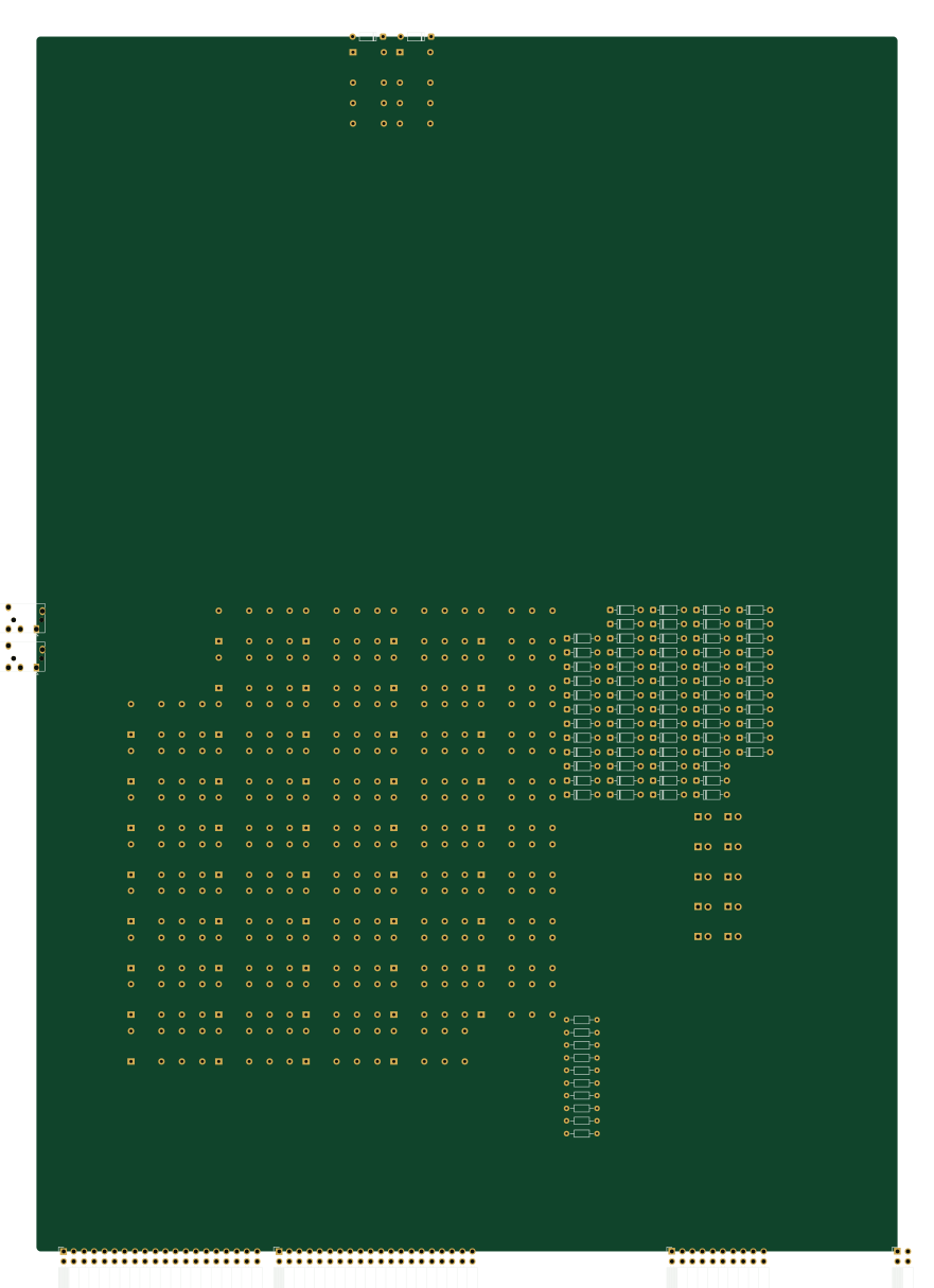
Tape loader
214.9 × 303.2 mm142 parts2LGPL-3.04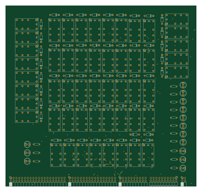
ALU V2
170.9 × 161.2 mm141 parts2LGPL-3.04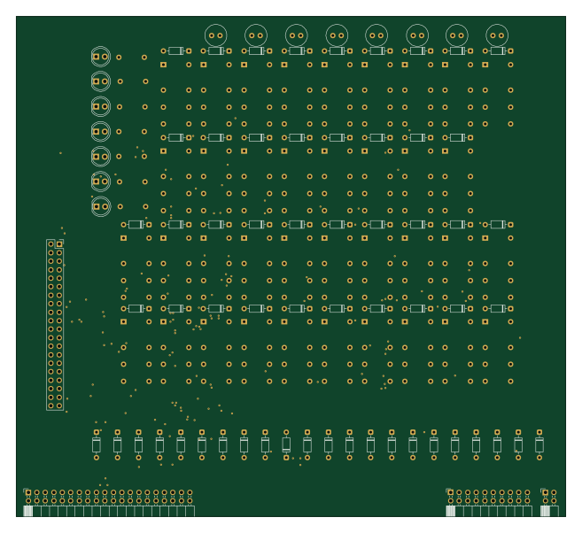
Front Panel V2
164 × 149.4 mm122 parts2LGPL-3.04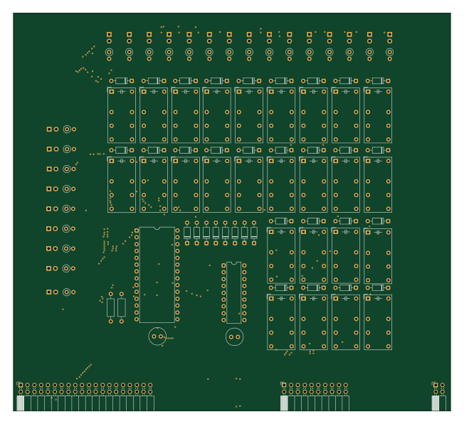
Memory V2
162.6 × 148 mm117 parts2LGPL-3.04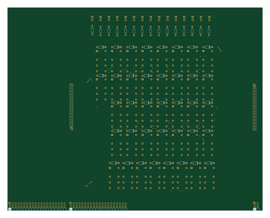
Incrementer V2
224.4 × 178.6 mm111 parts2LGPL-3.04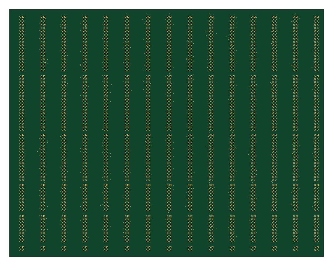
Bridge V2
282.7 × 222.9 mm90 parts2LGPL-3.04
Earlier revisions in the repo: Decoder