
Atari-Joystick-Tester

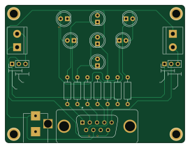
About the Atari-Joystick-Tester PCB
Atari-Joystick-Tester is an open source PCB design by tebl, published on GitHub under the GPL-3.0 license. It is a 2-layer board measuring 68 × 52.1 mm, with 24 components from 15 distinct parts.
By type, the board carries 8 connectors, 7 diodes, 7 resistors and 2 switches.
It belongs with the test & measurement designs in this gallery.
From the project
Simple joystick tester, can be used with the common Atari 9-pin joysticks and paddles (tested using multimeter).
Lately I've been going through my rather limited amount, but still designated a "sizable pile", of vintage joysticks. Maybe this was to be the year I got around to fixing them - given that we're constantly fast coming up on december, the time to get moving is definitively now. Did not want to subject one of my computers to all that plugging and unplugging while fiddling with wires and resoldering contacts, so the next step of procrastination was designing a simple joystick tester.
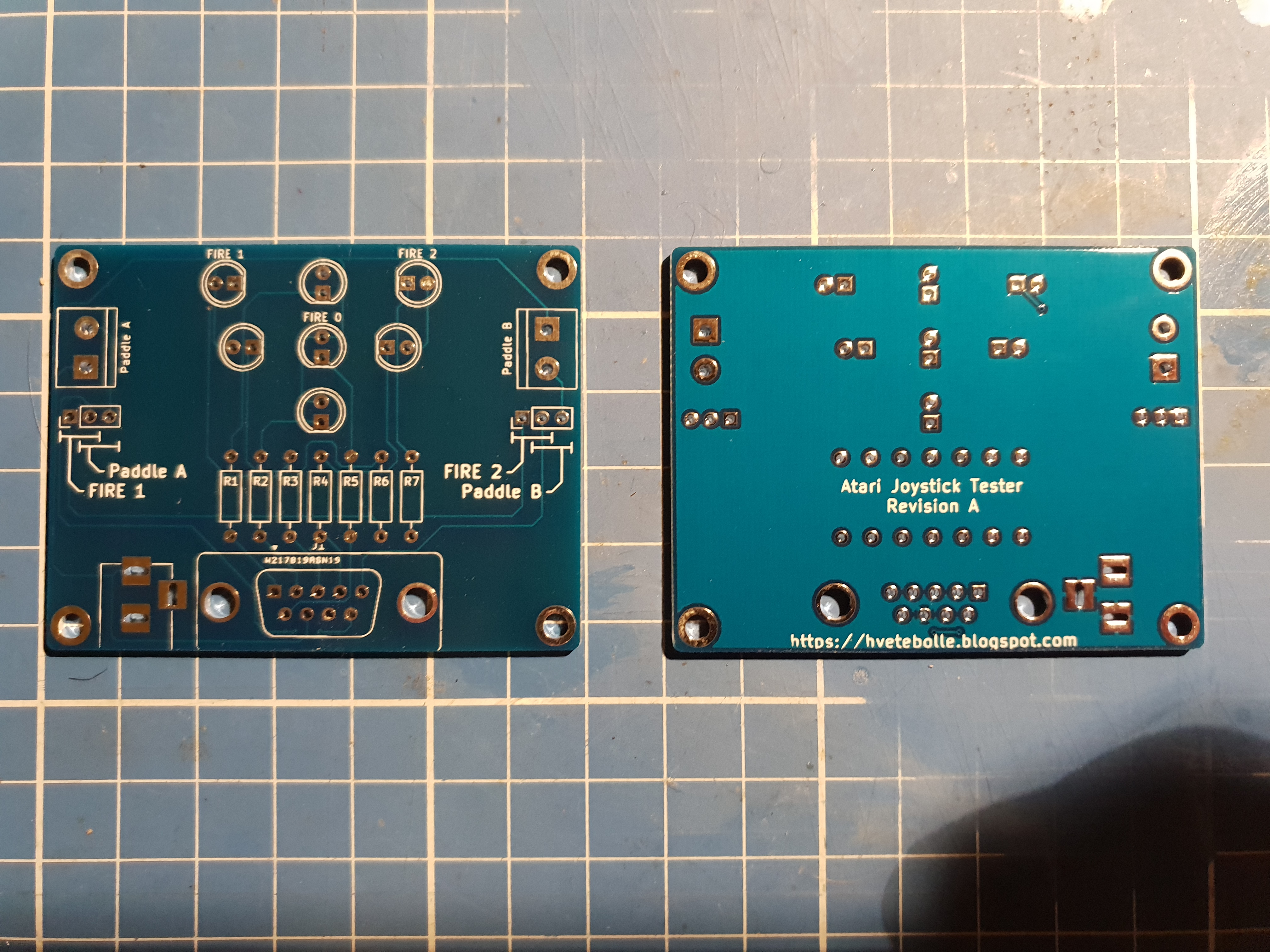
Atari-Joystick-Tester bill of materials (BOM)
24 components, 15 distinct parts.
| Qty | Part | Footprint | Refs |
|---|---|---|---|
| 1 | Atari_Joystick | DSUB-9_Male_Vertical_Pitch2.77x2.84mm | J1 |
| 1 | Paddle A | TerminalBlock_bornier-2_P5.08mm | J2 |
| 1 | Paddle B | TerminalBlock_bornier-2_P5.08mm | J3 |
| 1 | Barrel_Jack | BARREL_JACK | J4 |
| 4 | Mount | 1pin | J5, J6, J7, J8 |
| 1 | PADDLE A SEL. | Pin_Header_Straight_1x03_Pitch2.54mm | SW1 |
| 1 | PADDLE B SEL. | Pin_Header_Straight_1x03_Pitch2.54mm | SW2 |
| 1 | UP | LED_D5.0mm | D1 |
| 1 | DOWN | LED_D5.0mm | D2 |
| 1 | LEFT | LED_D5.0mm | D3 |
| 1 | RIGHT | LED_D5.0mm | D4 |
| 1 | FIRE 0 | LED_D5.0mm | D5 |
| 1 | FIRE 1 | LED_D5.0mm | D6 |
| 1 | FIRE 2 | LED_D5.0mm | D7 |
| 7 | 330 | R_Axial_DIN0207_L6.3mm_D2.5mm_P10.16mm_Horizontal | R1, R2, R3, R4, R5, R6, R7 |
Atari-Joystick-Tester design files
The KiCad project lives in the tebl/Atari-Joystick-Tester repository on GitHub; these links point at the commit this page was built from.
Atari-Joystick-Tester: common questions
How big is the Atari-Joystick-Tester PCB?
The Atari-Joystick-Tester measures 68 × 52.1 mm, has 2 copper layers and is 1.6 mm thick.
How many components are on the Atari-Joystick-Tester?
24 components, from 15 distinct parts. The full bill of materials is listed on this page.
Where can I download the Atari-Joystick-Tester design files?
From the tebl/Atari-Joystick-Tester repository on GitHub, which has the KiCad layout; the links under Design files point to each one.
Can I use the Atari-Joystick-Tester design in my own project?
Yes, under the terms of its GPL-3.0 license, which tebl chose for the repository.
Similar boards
LevelShifter
gusmanb
28.3 × 39.8 mm21 parts2LGPL-3.05.0k
StackLink
52.3 × 10.5 mm5 parts2LGPL-3.05.0k
AnalyzerBoxPCB fork
52.7 × 47.9 mm54 parts4LGPL-3.05.0k
EleLab v2 Bus100
Chrismettal
100 × 100 mm37 parts2LGPL-3.0528
EleLab v2 Bus150
150 × 50 mm37 parts2LGPL-3.0528
EleLab v2 PowerFeed
68 × 50 mm11 parts2LGPL-3.0528