
Soldered-TPS613222A-mini low power boost hardware design

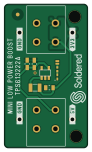
About the Soldered-TPS613222A-mini low power boost hardware design PCB
Soldered-TPS613222A-mini low power boost hardware design is an open source PCB design by test-gh-syncer2, published on GitHub under the TAPR-OHL-1.0 license. It is a 2-layer board measuring 22 × 38 mm, with 16 components from 10 distinct parts.
Other key parts include the TPS613222A. By type, the board carries 6 relays, 3 capacitors, 1 IC, 1 jumper, 1 diode and 1 inductor.
From the project
Hardware design, BOM, gerbers, 3D files and pinout for TPS613222A-mini-low-power-boost designed by Soldered.
All Soldered hardware is designed in KiCAD, and repositories are organized in the following way:
- CAD folder - contains KiCAD files (Schematics, Board, Panel Board), organized by version. Change log lists all changes between versions. - OUTPUTS - contains useful files, such as Bill of Materials (BOM), PDF of schematics, 3D .step file of the board and gerber files, organized by version.
Main components on the Soldered-TPS613222A-mini low power boost hardware design
Soldered-TPS613222A-mini low power boost hardware design bill of materials (BOM)
16 components, 10 distinct parts — part numbers from the project's BOM.
| Qty | Part | Footprint | Refs |
|---|---|---|---|
| 1 | TPS613222A | tps613222a | U1 |
| 2 | HOLE_3.2MM HOLE_3.2mm | HOLE_3.2mm | H1, H2 |
| 1 | SMD-JUMPER-CONNECTED_TRACE_SLODERMASK | SMD-JUMPER-CONNECTED_TRACE_SLODERMASK | JP1 |
| 4 | HEADER_MALE_1X1 | HEADER_MALE_1X1 | K1, K3, K4, K6 |
| 2 | TERMINAL_KF235-5.0-2P | TERMINAL_KF235-5.0-2P | K2, K5 |
| 1 | purple | 0402LED | D1 |
| 1 | DFE2016E-2R2M=P9 | DFE252012F-1R0M=P2 | L1 |
| 2 | CL10A226MP8NUNE | 0805C | C1, C2 |
| 1 | C1608X7S1A475K080AC | 0805C | C3 |
| 1 | 1k | 0402R | R1 |
Soldered-TPS613222A-mini low power boost hardware design design files
The KiCad project lives in the test-gh-syncer2/Soldered-TPS613222A-mini-low-power-boost-hardware-design repository on GitHub; these links point at the commit this page was built from.
Soldered-TPS613222A-mini low power boost hardware design: common questions
How big is the Soldered-TPS613222A-mini low power boost hardware design PCB?
The Soldered-TPS613222A-mini low power boost hardware design measures 22 × 38 mm, has 2 copper layers and is 1.6 mm thick.
How many components are on the Soldered-TPS613222A-mini low power boost hardware design?
16 components, from 10 distinct parts, with part numbers taken from the project's own BOM. The full bill of materials is listed on this page.
Where can I download the Soldered-TPS613222A-mini low power boost hardware design design files?
From the test-gh-syncer2/Soldered-TPS613222A-mini-low-power-boost-hardware-design repository on GitHub, which has the KiCad layout, the schematic and the BOM; the links under Design files point to each one.
Can I use the Soldered-TPS613222A-mini low power boost hardware design design in my own project?
Yes, under the terms of its TAPR-OHL-1.0 license, which test-gh-syncer2 chose for the repository.