
Radio Puck

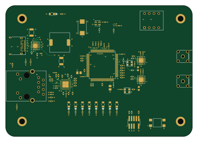
About the Radio Puck PCB
Radio Puck is an open source STM32 PCB design by thomas-montano, published on GitHub. It is a 8-layer board measuring 100 × 70 mm, with 154 components from 41 distinct parts.
Its main chip is the STM32F407VGT6, from the STM32 family. Other key parts include the SIT1566AC-JV-XXE-32.768D, ADP2164ACPZ-3.3-R7, SI4468-A2A-IM and DP83822IRHBR. By type, the board carries 70 resistors, 44 capacitors, 15 inductors, 9 LEDs, 6 ICs and 5 connectors.
It belongs with the rf & radio designs in this gallery.
From the project
Small STM32 based ethernet connected radio puck capable of full duplex transmit and receive as well as dual RX or dual TX. Capable of rates up to 1 Mbps and completely configurable for many kinds of different modes. This radio puck has been primarily designed to be your rubber duck that transmits a known signal while prototyping a receiver.
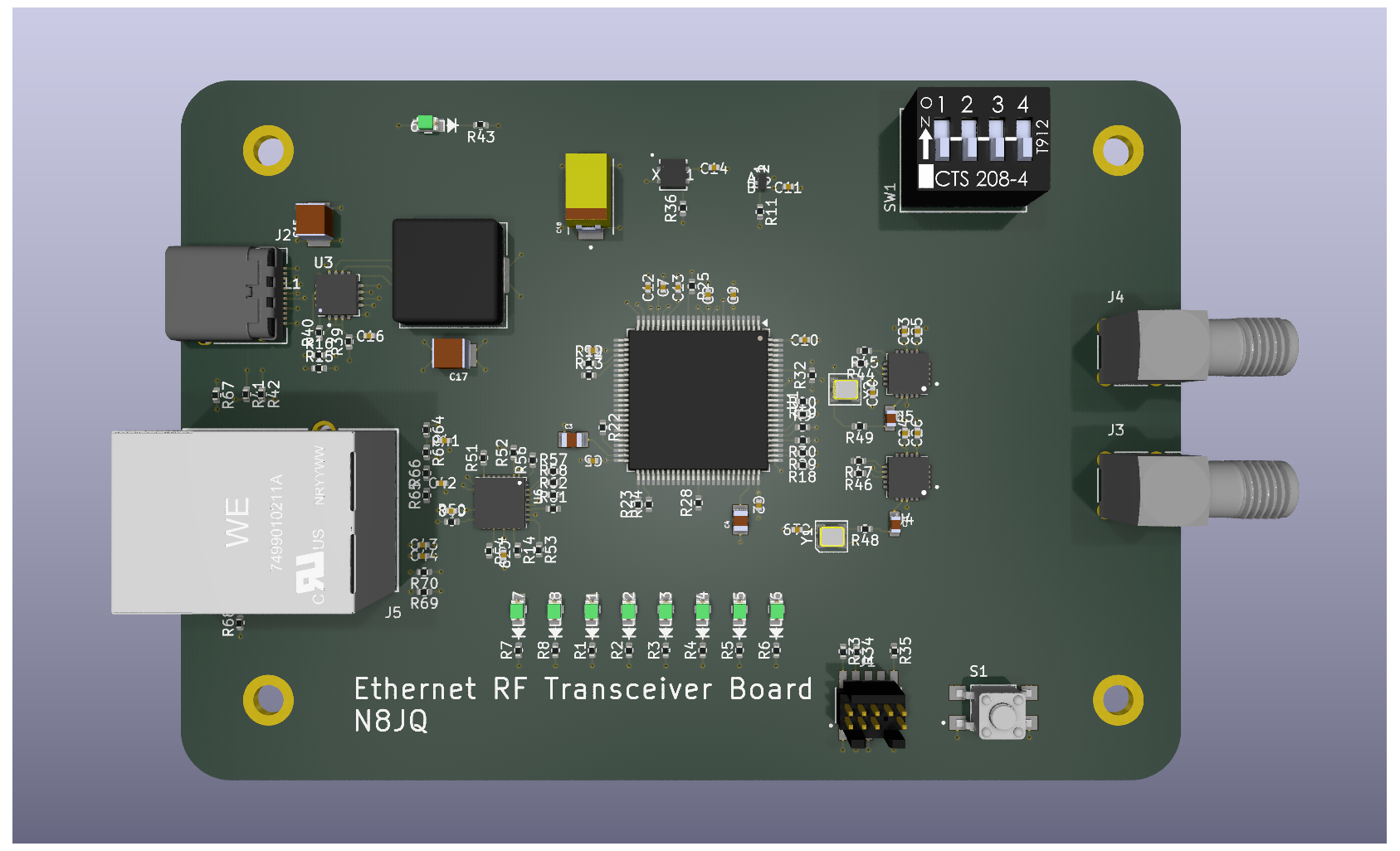
Main components on the Radio Puck
Radio Puck bill of materials (BOM)
154 components, 41 distinct parts.
| Qty | Part | Footprint | Refs |
|---|---|---|---|
| 1 | STM32F407VGT6 | LQFP-100_14x14mm_P0.5mm | U1 |
| 1 | SIT1566AC-JV-XXE-32.768D | BGA_E-32.768D_SIT | U2 |
| 1 | ADP2164ACPZ-3.3-R7 | QFN65P400X400X80-17N | U3 |
| 2 | SI4468-A2A-IM | QFN50P400X400X90-21N | U4, U5 |
| 1 | DP83822IRHBR | IC_DP83822IRHBR | U6 |
| 2 | TG2520SMN 30.0000M-MCGNNM0 | TG2520SMN | Y1, Y2 |
| 1 | FTSH-105-X-X-DV-007-P-X | SAMTEC_FTSH-105-X-X-DV-007-P-X | J1 |
| 1 | USB_C_Receptacle | USB_C_Receptacle_Amphenol_12401548E4-2A | J2 |
| 2 | 132225 | CONN_132225_AMP | J3, J4 |
| 1 | WE-RJ45_7499010211A | 7499010211A | J5 |
| 1 | TL3305AF160QG | SW_TL3305AF160QG | S1 |
| 1 | 208-4 | DIP8_208-4_CTS | SW1 |
| 1 | SIT5000AICGE-25MHz | SIT5000_2.7x2.4_SIT-M | XTAL1 |
| 9 | CMD17-21VGD/TR8 | LED0805N_CML-M | LED1, LED2, LED3, LED4, LED5, LED6, LED7, LED8 +1 |
| 1 | MSS1038-152NLC | L_Coilcraft_MSS1038-XXX | L1 |
| 2 | 100nH | L_0402_1005Metric | L2, L4 |
| 2 | 18nH | L_0402_1005Metric | L3, L5 |
| 4 | 22nH | L_0402_1005Metric | L6, L7, L12, L13 |
| 2 | 3.3nH | L_0402_1005Metric | L8, L9 |
| 4 | 11nH | L_0402_1005Metric | L10, L11, L14, L15 |
Show 21 more
| Qty | Part | Footprint | Refs |
|---|---|---|---|
| 25 | 100nF | CAPC10555_55N_KEM-L | C1, C2, C5, C6, C7, C8, C9, C10 +17 |
| 2 | 2.2uF | CAPC2012X140N | C3, C4 |
| 1 | 47uF | CAP_C3225X5R0J476M250AA | C15 |
| 1 | 100uF | CAP_C3225X5R0J107M250AB | C17 |
| 1 | 330uF | CAPPM7343X310N | C18 |
| 2 | 100 pF | CAPC1608X90N | C21, C22 |
| 2 | 3pF | C_01005_0402Metric | C27, C28 |
| 2 | 4.7pF | C_01005_0402Metric | C29, C31 |
| 2 | 1pF | C_01005_0402Metric | C30, C32 |
| 2 | 6.2nF | C_01005_0402Metric | C33, C34 |
| 4 | 3.3pF | C_01005_0402Metric | C35, C36, C37, C38 |
| 9 | 60 | R_0402_1005Metric | R1, R2, R3, R4, R5, R6, R7, R8 +1 |
| 44 | 40 | R_0402_1005Metric | R9, R10, R11, R12, R13, R14, R15, R16 +36 |
| 2 | 100k | R_0402_1005Metric | R31, R32 |
| 2 | 1K | R_0402_1005Metric | R37, R38 |
| 1 | 10 | R_0402_1005Metric | R39 |
| 1 | 10k | R_0402_1005Metric | R40 |
| 2 | 5.1k | R_0402_1005Metric | R41, R42 |
| 1 | 4.87k | R_0402_1005Metric | R50 |
| 6 | 49.9 | R_0402_1005Metric | R63, R64, R65, R66, R69, R70 |
| 2 | 2.49k | R_0402_1005Metric | R67, R68 |
Radio Puck design files
The KiCad project lives in the thomas-montano/Radio_Puck repository on GitHub; these links point at the commit this page was built from.
Radio Puck: common questions
What microcontroller does the Radio Puck use?
The Radio Puck is built around the STM32F407VGT6, from the STM32 family.
How big is the Radio Puck PCB?
The Radio Puck measures 100 × 70 mm, has 8 copper layers and is 1.175 mm thick.
How many components are on the Radio Puck?
154 components, from 41 distinct parts. The full bill of materials is listed on this page.
Where can I download the Radio Puck design files?
From the thomas-montano/Radio_Puck repository on GitHub, which has the KiCad layout and the schematic; the links under Design files point to each one.
Can I use the Radio Puck design in my own project?
The repository has no license, so all rights stay with thomas-montano. Use it as a reference, and ask the author before reusing the design.
Can I test firmware for the Radio Puck without the hardware?
Yes. HardLabs builds a simulation of the board from its netlist and BOM, so you can run and debug STM32 firmware against it before you order a PCB.
Similar boards
 STM32
LumenPnP Motherboard
opulo-inc
149 × 95 mm296 parts4LCC-BY-SA-4.03.7k STM32
Type g
google
169 × 30 mm24 parts2LApache-2.02.9k STM32
Base
52.3 × 52.3 mm36 parts2LApache-2.02.9k STM32
Type a
150 × 30 mm14 parts2LApache-2.02.9k STM32
Main panel
234 × 84 mm26 parts4LApache-2.02.9k STM32
Type c
188 × 30 mm17 parts2LApache-2.02.9k