
Fan test adapter

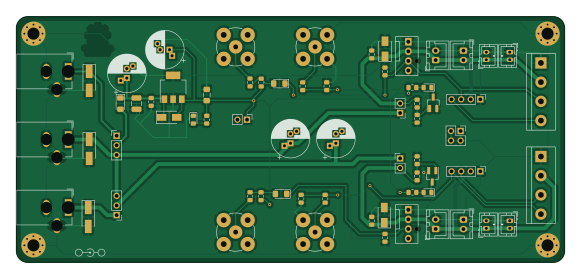
About the Fan test adapter PCB
Fan test adapter is an open source PCB design by tjko, published on GitHub under the GPL-3.0 license. It is a 2-layer board measuring 145 × 65 mm, with 68 components from 47 distinct parts.
Other key parts include the SPX2954-3.3. By type, the board carries 16 connectors, 15 resistors, 12 diodes, 11 capacitors, 4 jumpers and 2 transistors.
It belongs with the test & measurement designs in this gallery.
From the project
Adapter PCB board for easily testing PC (PWM) fans.
Adapter was created to simplify characterising PC fans. It's mainly meant for PWM fans, but can also be useful for 3-pin PC fans. Adapter also has common JST connectors for common 2-pin fans. This adapter was used in development and testing of Fanpico (Fanpico is a smart PWM fan controller) to "emulate" motherboard FAN outputs.
Adapter is meant to be used with 3 channel programmable power supply (but will work fine with 1 or 2 channel PSUs) 2+ channel oscilloscope (or frequency counter) * 2 channel signal generator
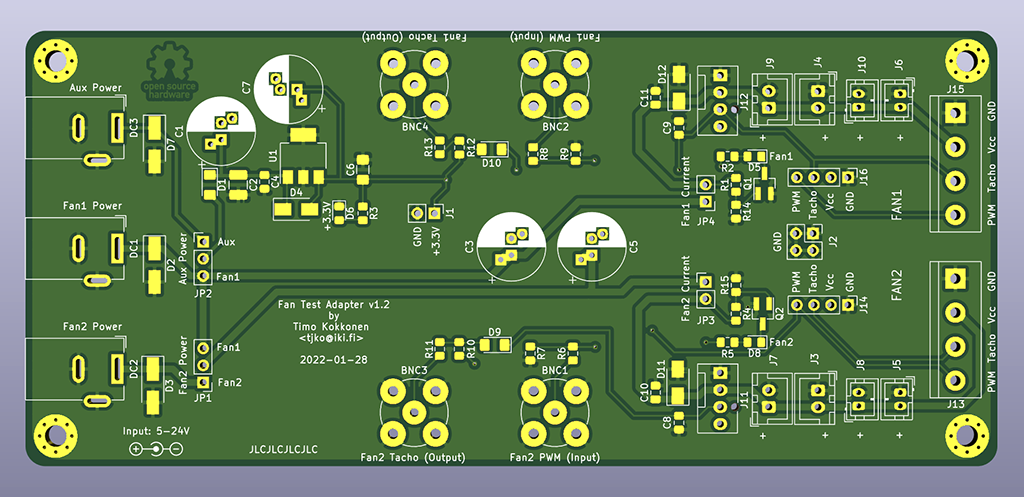
Main components on the Fan test adapter
Fan test adapter bill of materials (BOM)
68 components, 47 distinct parts — part numbers from the project's BOM.
| Qty | Part | Footprint | Refs |
|---|---|---|---|
| 1 | SPX2954-3.3 | SOT-223-3_TabPin2 | U1 |
| 2 | 2N7002K | SOT-23_Handsoldering | Q1, Q2 |
| 1 | 3.3V Output | PinHeader_1x02_P2.54mm_Vertical | J1 |
| 1 | Extra GND Pins | PinHeader_2x02_P2.54mm_Vertical | J2 |
| 1 | CONN_01X02_MALE Fan2_JST2 | JST_XH_B2B-XH-A_1x02_P2.50mm_Vertical | J3 |
| 1 | CONN_01X02_MALE Fan1_JST2 | JST_XH_B2B-XH-A_1x02_P2.50mm_Vertical | J4 |
| 1 | CONN_01X02_MALE Fan2_JST4 | JST_PH_B2B-PH-K_1x02_P2.00mm_Vertical | J5 |
| 1 | CONN_01X02_MALE Fan1_JST4 | JST_PH_B2B-PH-K_1x02_P2.00mm_Vertical | J6 |
| 1 | CONN_01X02_MALE Fan2_JST1 | JST_XH_B2B-XH-A_1x02_P2.50mm_Vertical | J7 |
| 1 | CONN_01X02_MALE Fan2_JST3 | JST_PH_B2B-PH-K_1x02_P2.00mm_Vertical | J8 |
| 1 | CONN_01X02_MALE Fan1_JST1 | JST_XH_B2B-XH-A_1x02_P2.50mm_Vertical | J9 |
| 1 | CONN_01X02_MALE Fan1_JST3 | JST_PH_B2B-PH-K_1x02_P2.00mm_Vertical | J10 |
| 1 | FAN_CPU_4PIN Fan2 Molex | FanPinHeader_1x04_P2.54mm_Vertical | J11 |
| 1 | FAN_CPU_4PIN Fan1 Molex | FanPinHeader_1x04_P2.54mm_Vertical | J12 |
| 1 | CONN_01X04_MALE Fan2_Terminal | TerminalBlock_bornier-4_P5.08mm | J13 |
| 1 | Fan2_Header | PinHeader_1x04_P2.54mm_Vertical | J14 |
| 1 | CONN_01X04_MALE Fan1_Terminal | TerminalBlock_bornier-4_P5.08mm | J15 |
| 1 | Fan1_Header | PinHeader_1x04_P2.54mm_Vertical | J16 |
| 1 | 5-1634503-1 Fan2 PWM (Input) TE | BNC_TEConnectivity_1478204_Vertical | BNC1 |
| 1 | 5-1634503-1 Fan1 PWM (Input) TE | BNC_TEConnectivity_1478204_Vertical | BNC2 |
Show 27 more
| Qty | Part | Footprint | Refs |
|---|---|---|---|
| 1 | 5-1634503-1 Fan2 Tacho (Output) TE | BNC_TEConnectivity_1478204_Vertical | BNC3 |
| 1 | 5-1634503-1 Fan1 Tacho (Output) TE | BNC_TEConnectivity_1478204_Vertical | BNC4 |
| 1 | Fan1 Power | BarrelJack_Wuerth_6941xx301002 | DC1 |
| 1 | Fan2 Power | BarrelJack_Wuerth_6941xx301002 | DC2 |
| 1 | Aux Power | BarrelJack_Wuerth_6941xx301002 | DC3 |
| 1 | Fan2 Power | PinHeader_1x03_P2.54mm_Vertical | JP1 |
| 1 | Aux Power | PinHeader_1x03_P2.54mm_Vertical | JP2 |
| 1 | Fan2 Current | PinHeader_1x02_P2.54mm_Vertical | JP3 |
| 1 | Fan1 Currrent | PinHeader_1x02_P2.54mm_Vertical | JP4 |
| 3 | SM5819PL-TP | D_1206_3216Metric_Pad1.42x1.75mm_HandSolder | D1, D9, D10 |
| 3 | SBRT5A50SA | D_SMA_Handsoldering | D2, D3, D7 |
| 3 | FM4007W | D_SMA | D4, D11, D12 |
| 3 | LED | LED_0805_2012Metric_Pad1.15x1.40mm_HandSolder | D5, D6, D8 |
| 1 | 10uF 35V | CP_Radial_D10.0mm_P2.50mm_P5.00mm | C1 |
| 1 | 581-TAJB475K035R 4.7uF 35V | C_1210_3225Metric_Pad1.42x2.65mm_HandSolder | C2 |
| 2 | DNF | CP_Radial_D10.0mm_P2.50mm_P5.00mm | C3, C5 |
| 1 | 0.1uF 35V | C_0805_2012Metric_Pad1.15x1.40mm_HandSolder | C4 |
| 1 | 10uF | C_1206_3216Metric_Pad1.42x1.75mm_HandSolder | C6 |
| 1 | 10uF | CP_Radial_D10.0mm_P2.50mm_P5.00mm | C7 |
| 2 | 1NF 1nF | C_0805_2012Metric_Pad1.15x1.40mm_HandSolder | C8, C9 |
| 2 | 0.1uF | C_0805_2012Metric_Pad1.15x1.40mm_HandSolder | C10, C11 |
| 2 | 100K 10k | R_0805_2012Metric_Pad1.15x1.40mm_HandSolder | R1, R4 |
| 3 | 5k | R_0805_2012Metric_Pad1.15x1.40mm_HandSolder | R2, R3, R5 |
| 4 | 1k | R_0805_2012Metric_Pad1.15x1.40mm_HandSolder | R6, R8, R11, R13 |
| 2 | 33K 33k | R_0805_2012Metric_Pad1.15x1.40mm_HandSolder | R7, R9 |
| 2 | 10K 10k | R_0805_2012Metric_Pad1.15x1.40mm_HandSolder | R10, R12 |
| 2 | 1M | R_0805_2012Metric_Pad1.15x1.40mm_HandSolder | R14, R15 |
Fan test adapter design files
The KiCad project lives in the tjko/fan-test-adapter repository on GitHub; these links point at the commit this page was built from.
Fan test adapter: common questions
How big is the Fan test adapter PCB?
The Fan test adapter measures 145 × 65 mm, has 2 copper layers and is 1.6 mm thick.
How many components are on the Fan test adapter?
68 components, from 47 distinct parts, with part numbers taken from the project's own BOM. The full bill of materials is listed on this page.
Where can I download the Fan test adapter design files?
From the tjko/fan-test-adapter repository on GitHub, which has the KiCad layout and the BOM; the links under Design files point to each one.
Can I use the Fan test adapter design in my own project?
Yes, under the terms of its GPL-3.0 license, which tjko chose for the repository.
Similar boards
DB9 High-Low Signal Generator
nanographs
47 × 30 mm10 parts2LNo license370
OneInchEye
will127534
39 × 39 mm79 parts4LMIT346
Integralstick mead
azonenberg
65 × 51.5 mm19 parts4LBSD-3-Clause193
Hmcad characterization
57 × 85 mm58 parts4LBSD-3-Clause193
Iob characterization v02
74.5 × 31 mm123 parts4LBSD-3-Clause193
Pmod prbs slow
41 × 20 mm43 parts4LBSD-3-Clause193