
Chibi-T Furoshiki AutoAirAdjust

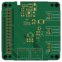
About the Chibi-T Furoshiki AutoAirAdjust PCB
Chibi-T Furoshiki AutoAirAdjust is an open source PCB design by todateman, published on GitHub under the MIT license. It is a 2-layer board measuring 50 × 50 mm, with 30 components from 22 distinct parts.
Other key parts include the MP1584EN-LF-Z and ADS1015IDGS. By type, the board carries 10 resistors, 8 capacitors, 5 connectors, 2 ICs, 2 diodes and 1 transistor.
From the project
M5Stack Basic / Core2 用の空気圧自動調整コントローラー基板の KiCad プロジェクトです。 1次側・2次側の空気圧センサと燃圧センサの値を M5Stack で監視し、ソレノイドバルブの開閉によって 1次側から2次側への圧縮空気の流れを自動制御します。
M5Stack Basic / Core2 用の空気圧自動調整コントローラー基板の KiCad プロジェクトです。 1次側・2次側の空気圧センサと燃圧センサの値を M5Stack で監視し、ソレノイドバルブの開閉によって 1次側から2次側への圧縮空気の流れを自動制御します。
- 対応ホスト: M5Stack Basic / Core2(MBUS 30pin コネクタで直結するスタック型基板) - センサ入力 - 1次側・2次側 空気圧センサ:DFRobot Gravity MPX5700AP (SEN0456) × 2 個 (センサ自体はアナログ出力のため、 I2C ADC モジュール経由で Grove I2C バスに接続) - 燃圧センサ:0–1.0 MPa / 0.5–4.5V アナログ出力タイプ 1 個 (基板上の 12bit ADC(ADS1015)で読み取り) - アクチュエータ出力:DC12Vソレノイドバルブ 1 系統(1次側→2次側の圧縮空気の開閉弁を GPIO トリガーで駆動) - 電源:車両/バッテリーの 12V 入力から基板上の降圧コンバータで 5V を生成し、 M5Stack と各センサへ供給
Main components on the Chibi-T Furoshiki AutoAirAdjust
Chibi-T Furoshiki AutoAirAdjust bill of materials (BOM)
30 components, 22 distinct parts — part numbers from the project's BOM.
| Qty | Part | Footprint | Refs |
|---|---|---|---|
| 1 | MP1584EN-LF-Z MPS(芯源) | SOIC-8_L5.0-W4.0-P1.27-LS6.0-BL-EP2.0 | U1 |
| 1 | ADS1015IDGS | TSSOP-10_3x3mm_P0.5mm | U2 |
| 1 | AO3400A | SOT-23 | Q1 |
| 1 | M-BUS | BF@M5Stack_MBUS | J1 |
| 1 | FROM_12V_POWER from_12V_Power | JST_XH_S2B-XH-A_1x02_P2.50mm_Horizontal | J2 |
| 1 | PRESSURE_SEN | JST_XH_S3B-XH-A_1x03_P2.50mm_Horizontal | J4 |
| 1 | I2C | GROVE-HW4-2.0-90D | J6 |
| 1 | SOLENOID | JST_XH_S2B-XH-A_1x02_P2.50mm_Horizontal | J7 |
| 1 | C1884489 Polyfuse_Small | Fuse_1812_4532Metric | F1 |
| 1 | C22452 D_Schottky | D_SMA | D1 |
| 1 | 1N4148WS | D_SOD-323 | D2 |
| 1 | 10UH 10uH | L_Sunlord_SWPA3015S | L1 |
| 1 | 100UF 100uF | C_1206_3216Metric | C1 |
| 3 | 22UF 22uF | C_0603_1608Metric | C2, C3, C4 |
| 1 | 150PF 150pF | C_0603_1608Metric | C5 |
| 2 | 2.2UF 2.2uF | C_0805_2012Metric | C6, C7 |
| 1 | 0.1UF 0.1uF | C_0402_1005Metric | C8 |
| 1 | 52.3K 52.3k | R_0603_1608Metric | R1 |
| 3 | 100K 100k | R_0603_1608Metric | R2, R4, R10 |
| 4 | 10K 10k | R_0805_2012Metric | R3, R5, R6, R7 |
Show 2 more
| Qty | Part | Footprint | Refs |
|---|---|---|---|
| 1 | 1k | R_0805_2012Metric | R8 |
| 1 | 12K 12k | R_0805_2012Metric | R9 |
Chibi-T Furoshiki AutoAirAdjust design files
The KiCad project lives in the todateman/Chibi-T_Furoshiki_AutoAirAdjust_PCB repository on GitHub; these links point at the commit this page was built from.
Chibi-T Furoshiki AutoAirAdjust: common questions
How big is the Chibi-T Furoshiki AutoAirAdjust PCB?
The Chibi-T Furoshiki AutoAirAdjust measures 50 × 50 mm, has 2 copper layers and is 1.6 mm thick.
How many components are on the Chibi-T Furoshiki AutoAirAdjust?
30 components, from 22 distinct parts, with part numbers taken from the project's own BOM. The full bill of materials is listed on this page.
Where can I download the Chibi-T Furoshiki AutoAirAdjust design files?
From the todateman/Chibi-T_Furoshiki_AutoAirAdjust_PCB repository on GitHub, which has the KiCad layout, the schematic and the BOM; the links under Design files point to each one.
Can I use the Chibi-T Furoshiki AutoAirAdjust design in my own project?
Yes, under the terms of its MIT license, which todateman chose for the repository.