
ZAIR

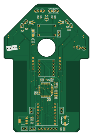
About the ZAIR PCB
ZAIR is an open source STM32 PCB design by zischl, published on GitHub. It is a 2-layer board measuring 77 × 115 mm, with 68 components from 43 distinct parts.
Its main chip is the STM32F405RGT6, from the STM32 family. Other key parts include the LSM6DSV-BREAKOUT, MT6701-L-01355, MT6701-R-01355, AMS1117-3.3 and MP2307-MINI360-MODULE. By type, the board carries 23 resistors, 13 capacitors, 10 transistors, 8 diodes, 7 ICs and 5 connectors.
It belongs with the robotics & motion, power & battery and sensors designs in this gallery.
From the project
MicroMouse Build !
A custom 4WD vacuum micromouse built for the Sri Lanka IIT Micro Maze 3.0 competition (IEEE 16×16).
The PCB also serves as the robot's structural chassis, with cutouts for the drive wheels and a central aperture for a 1020 coreless motor suction fan.
- MCU: STM32F405RGT6 (ARM Cortex-M4 @ 168MHz) - Drive Motors: 2× Coreless 1718 motors - Motor Driver: TB6612FNG breakout (red module) - Vacuum Fan: Coreless 1020 motor switched by an AO3400 N-MOSFET + SS14 flyback diode - IMU: LSM6DSV breakout (SPI2) - Encoders: 2× MT6701 magnetic encoders (vertical 90° mounts, ABZ quadrature mode to TIM2/TIM3)…
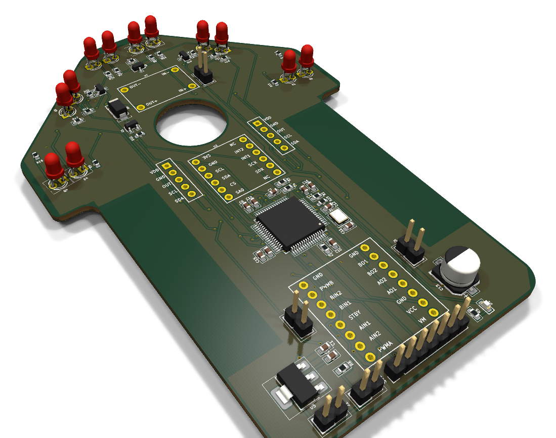
Main components on the ZAIR
ZAIR bill of materials (BOM)
68 components, 43 distinct parts — part numbers from the project's BOM.
| Qty | Part | Footprint | Refs |
|---|---|---|---|
| 1 | STM32F405RGT6 | LQFP-64_10x10mm_P0.5mm | U1 |
| 1 | LSM6DSV-BREAKOUT | LSM6DSV_Breakout | U2 |
| 1 | MT6701-L-01355 | MT6701_Breakout | U3 |
| 1 | MT6701-R-01355 | MT6701_Breakout | U4 |
| 1 | AMS1117-3.3 | SOT-223-3_TabPin2 | U5 |
| 1 | MP2307-MINI360-MODULE | MP2307_Mini360_Buck | U7 |
| 1 | TB6612FNG-BREAKOUT | TB6612FNG_Breakout_Red | U8 |
| 1 | AO3400_VAC | SOT-23 | Q1 |
| 1 | TEFT4300_FL | LED_D3.0mm | Q2 |
| 1 | TEFT4300_FR | LED_D3.0mm | Q3 |
| 1 | TEFT4300_L | LED_D3.0mm | Q4 |
| 1 | TEFT4300_R | LED_D3.0mm | Q5 |
| 1 | TEFT4300_DL | LED_D3.0mm | Q6 |
| 1 | TEFT4300_DR | LED_D3.0mm | Q7 |
| 1 | AO3400_FRONT | SOT-23 | Q8 |
| 1 | AO3400_SIDE | SOT-23 | Q9 |
| 1 | AO3400_DIAG | SOT-23 | Q10 |
| 1 | 8MHZ 8MHz | Crystal_SMD_3225-4Pin_3.2x2.5mm | X1 |
| 1 | VBAT_IN | PinHeader_1x02_P2.54mm_Vertical | J1 |
| 1 | VAC_MOTOR | PinHeader_1x02_P2.54mm_Vertical | J3 |
Show 23 more
| Qty | Part | Footprint | Refs |
|---|---|---|---|
| 1 | MOT_LEFT | PinHeader_1x02_P2.54mm_Vertical | J4 |
| 1 | MOT_RIGHT | PinHeader_1x02_P2.54mm_Vertical | J5 |
| 1 | SWD_UART_SWO | PinHeader_1x07_P2.54mm_Vertical | J7 |
| 1 | USER_BTN | PinHeader_1x02_P2.54mm_Vertical | SW1 |
| 1 | LED_BLUE | LED_0603_1608Metric | D1 |
| 1 | SFH4545_FL | LED_D3.0mm | D2 |
| 1 | SFH4545_FR | LED_D3.0mm | D3 |
| 1 | SFH4545_L | LED_D3.0mm | D4 |
| 1 | SFH4545_R | LED_D3.0mm | D5 |
| 1 | SFH4545_DL | LED_D3.0mm | D6 |
| 1 | SFH4545_DR | LED_D3.0mm | D7 |
| 1 | SS14_FLYBACK | D_SMA | D8 |
| 2 | 10UF 10uF | C_0603_1608Metric | C1, C2 |
| 5 | 100NF 100nF | C_0603_1608Metric | C7, C8, C9, C10, C16 |
| 2 | 20PF 20pF | C_0603_1608Metric | C11, C12 |
| 1 | 100UF 100uF | CP_Elec_6.3x5.4 | C13 |
| 2 | 2.2UF 2.2uF | C_0603_1608Metric | C14, C15 |
| 1 | 1UF 1uF | C_0603_1608Metric | C17 |
| 14 | 10K 10k | R_0603_1608Metric | R1, R2, R4, R6, R13, R14, R15, R16 +6 |
| 1 | 22K 22k | R_0603_1608Metric | R3 |
| 1 | 330 | R_0603_1608Metric | R5 |
| 6 | 33 | R_0603_1608Metric | R7, R8, R9, R10, R11, R12 |
| 1 | 0R/10R | R_0603_1608Metric | R23 |
ZAIR design files
The KiCad project lives in the zischl/ZAIR repository on GitHub; these links point at the commit this page was built from.
ZAIR: common questions
What microcontroller does the ZAIR use?
The ZAIR is built around the STM32F405RGT6, from the STM32 family.
How big is the ZAIR PCB?
The ZAIR measures 77 × 115 mm, has 2 copper layers and is 1.6 mm thick.
How many components are on the ZAIR?
68 components, from 43 distinct parts, with part numbers taken from the project's own BOM. The full bill of materials is listed on this page.
Where can I download the ZAIR design files?
From the zischl/ZAIR repository on GitHub, which has the KiCad layout, the schematic and the BOM; the links under Design files point to each one.
Can I use the ZAIR design in my own project?
The repository has no license, so all rights stay with zischl. Use it as a reference, and ask the author before reusing the design.
Can I test firmware for the ZAIR without the hardware?
Yes. HardLabs builds a simulation of the board from its netlist and BOM, so you can run and debug STM32 firmware against it before you order a PCB.
Similar boards
 STM32
LumenPnP Motherboard
opulo-inc
149 × 95 mm296 parts4LCC-BY-SA-4.03.7k STM32
Type g
google
169 × 30 mm24 parts2LApache-2.02.9k STM32
Base
52.3 × 52.3 mm36 parts2LApache-2.02.9k STM32
Main panel
234 × 84 mm26 parts4LApache-2.02.9k STM32
Type a
150 × 30 mm14 parts2LApache-2.02.9k STM32
Type c
188 × 30 mm17 parts2LApache-2.02.9k