
Led test

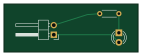
About the Led test PCB
Led test is an open source PCB design by zymaxcii, published on GitHub. It is a 2-layer board measuring 35.6 × 12.7 mm, with 3 components from 3 distinct parts.
By type, the board carries 1 battery holder, 1 diode and 1 resistor.
From the project
My arduino playground
Led test bill of materials (BOM)
3 components, 3 distinct parts — part numbers from the project's BOM.
| Qty | Part | Footprint | Refs |
|---|---|---|---|
| 1 | 5V | PinHeader_1x02_P2.54mm_Horizontal | BT1 |
| 1 | 863-1N4001G LED 2V | LED_D3.0mm | D1 |
| 1 | 603-MFR-25FBF52-470R 330 | R_Axial_DIN0204_L3.6mm_D1.6mm_P5.08mm_Horizontal | R1 |
Led test design files
The KiCad project lives in the zymaxcii/sketch repository on GitHub; these links point at the commit this page was built from.
Led test: common questions
How big is the Led test PCB?
The Led test measures 35.6 × 12.7 mm, has 2 copper layers and is 1.6 mm thick.
How many components are on the Led test?
3 components, from 3 distinct parts, with part numbers taken from the project's own BOM. The full bill of materials is listed on this page.
Where can I download the Led test design files?
From the zymaxcii/sketch repository on GitHub, which has the KiCad layout and the BOM; the links under Design files point to each one.
Can I use the Led test design in my own project?
The repository has no license, so all rights stay with zymaxcii. Use it as a reference, and ask the author before reusing the design.
More boards in sketch
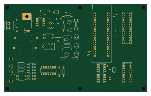
SERIAL PIC PROGRAMMER
160 × 99.1 mm55 partsNo license1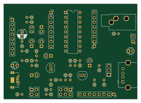
Beep BRRR
70 × 50 mm46 parts2LNo license1 AVR/Arduino
Arduino-Pro-Mini
17.8 × 33 mm24 parts2LNo license1
8-Led
23.2 × 31.5 mm17 parts2LNo license1
5LED-TH
40.6 × 30.5 mm11 parts2LNo license1
Ds1307
30.4 × 24.1 mm10 parts16LNo license1
555 Timer LED Flasher
61 × 25.4 mm8 parts2LNo license1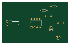
555 Blinker
59.7 × 36.8 mm8 parts2LNo license1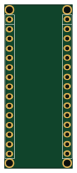
Nano
17.8 × 43.2 mm6 parts2LNo license1
1LED-TH
28.5 × 15.2 mm3 parts2LNo license1