
137 MHz LC band pass filter

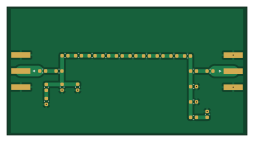
About the 137 MHz LC band pass filter PCB
137 MHz LC band pass filter is an open source PCB design by aaron-james-oommen, published on GitHub under the MIT license. It is a 2-layer board measuring 63.4 × 33.8 mm, with 24 components from 3 distinct parts.
By type, the board carries 20 capacitors, 2 connectors and 2 inductors.
It belongs with the rf & radio designs in this gallery.
From the project
A 137 MHz LC band-pass filter PCB designed for satellite communication and SDR applications, including NOAA weather satellite reception
A compact 137 MHz LC band-pass filter designed for RF applications, particularly satellite and SDR reception.
This project contains the complete PCB design and manufacturing files for a 137 MHz LC band-pass filter.
The filter is intended to provide band selection around the 137 MHz frequency range and can be used as an RF front-end filter for applications such as weather satellite reception and Software Defined Radio (SDR).
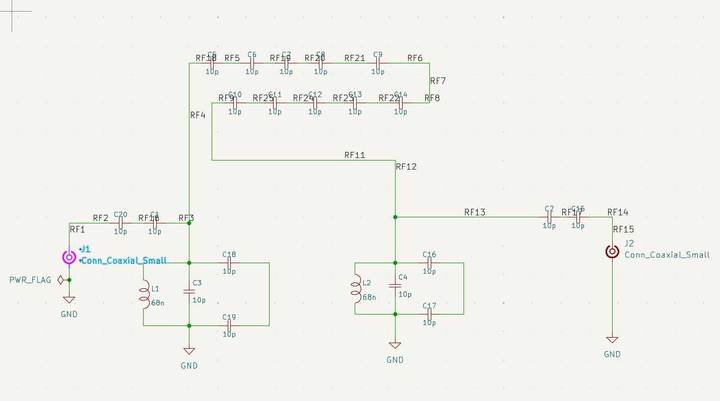
137 MHz LC band pass filter bill of materials (BOM)
24 components, 3 distinct parts.
| Qty | Part | Footprint | Refs |
|---|---|---|---|
| 2 | Conn_Coaxial_Small | SMA_Amphenol_132289_EdgeMount | J1, J2 |
| 2 | 68n | L_0603_1608Metric | L1, L2 |
| 20 | 10p | C_0603_1608Metric | C1, C2, C3, C4, C5, C6, C7, C8 +12 |
137 MHz LC band pass filter design files
The KiCad project lives in the aaron-james-oommen/137_MHz_LC_band_pass_filter repository on GitHub; these links point at the commit this page was built from.
- LayoutKiCad/final_filter.kicad_pcb
- SchematicKiCad/final_filter.kicad_sch
137 MHz LC band pass filter: common questions
How big is the 137 MHz LC band pass filter PCB?
The 137 MHz LC band pass filter measures 63.4 × 33.8 mm, has 2 copper layers and is 1.6 mm thick.
How many components are on the 137 MHz LC band pass filter?
24 components, from 3 distinct parts. The full bill of materials is listed on this page.
Where can I download the 137 MHz LC band pass filter design files?
From the aaron-james-oommen/137_MHz_LC_band_pass_filter repository on GitHub, which has the KiCad layout and the schematic; the links under Design files point to each one.
Can I use the 137 MHz LC band pass filter design in my own project?
Yes, under the terms of its MIT license, which aaron-james-oommen chose for the repository.
Similar boards
Hat
pa3gsb
65 × 56 mm81 parts2LNo license675
Radioberry juice
65 × 56 mm87 parts2LNo license675
Radioberry preamp
65 × 56 mm137 parts2LNo license675
Goodwatch20
travisgoodspeed
25.6 × 27.6 mm20 parts2LNo license568
GoodPocketWatch
75.2 × 101.2 mm56 parts2LNo license568
Goodwatch31
25.6 × 27.6 mm23 parts2LNo license568