
RobotInterfaceBoard

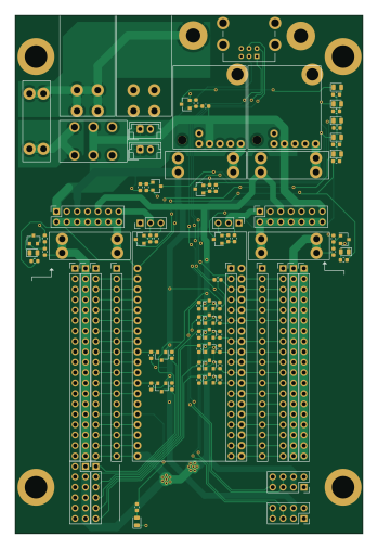
About the RobotInterfaceBoard PCB
RobotInterfaceBoard is an open source PCB design by acamilo, published on GitHub. It is a 4-layer board measuring 84.8 × 126.3 mm, with 93 components from 18 distinct parts.
Other key parts include the polulu-3784-D36V28F7, esp-devkit and DPDT_x2. By type, the board carries 39 resistors, 22 connectors, 15 transistors, 8 diodes, 5 fuses and 4 ICs.
It belongs with the robotics & motion and iot & wireless designs in this gallery.
From the project
The Robot Interface Board (RIB) is a breakout board for the ESP32-DevKitC Arduino module. The Dev Kit C is a reference design of the ESP32-WROOM-32 module which houses the WiFi and bluetooth Antenae. The ESP32-WROOM-32 module houses an ESP32 microcontroller.
The Robot Interface Board (RIB) is a breakout board for the ESP32-DevKitC Arduino module. The Dev Kit C is a reference design of the ESP32-WROOM-32 module which houses the WiFi and bluetooth Antenae. The ESP32-WROOM-32 module houses an ESP32 microcontroller.
ESP32-DevKitC Arduino module wireing diagram
There are 16 I/O pins availible for use in your programs with no external perpheral already using them.
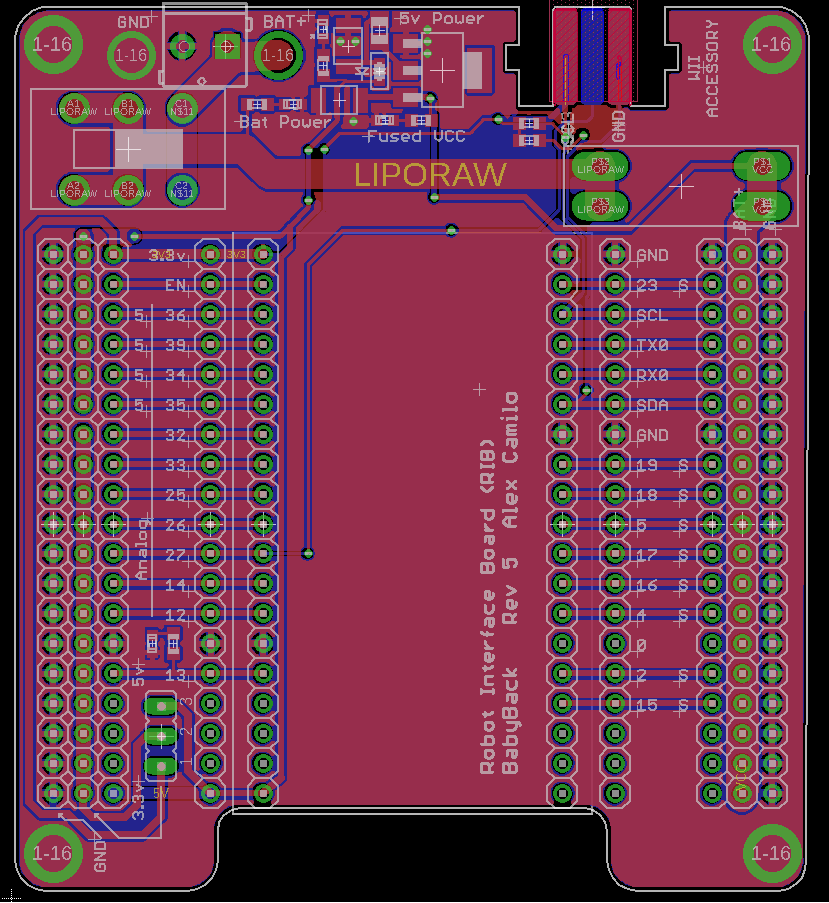
Main components on the RobotInterfaceBoard
RobotInterfaceBoard bill of materials (BOM)
93 components, 18 distinct parts — part numbers from the project's BOM.
| Qty | Part | Footprint | Refs |
|---|---|---|---|
| 2 | polulu-3784-D36V28F7 | polulu-3784-D36V28F7 | U1, U2 |
| 1 | esp-devkit | ESP-DEVKIT | U3 |
| 1 | DPDT_x2 | GF-126-0327 | U4 |
| 15 | BSS138 | SOT-23 | Q1, Q2, Q3, Q4, Q5, Q6, Q7, Q8 +7 |
| 2 | Conn_01x03 | PinHeader_1x03_P2.54mm_Vertical | J1, J9 |
| 2 | Conn_01x02_Female | JST_EH_B2B-EH-A_1x02_P2.50mm_Vertical | J2, J6 |
| 9 | Conn_01x19 | PinHeader_1x19_P2.54mm_Vertical | J3, J5, J7, J10, J13, J16, J19, J20 +1 |
| 2 | Conn_02x07_Odd_Even | PinSocket_2x07_P2.54mm_Vertical | J4, J8 |
| 2 | Conn_01x01_Male | P315100rH | J11, J26 |
| 2 | Conn_02x04_Odd_Even | PinSocket_2x04_P2.54mm_Vertical | J14, J15 |
| 1 | Conn_01x06 | PinHeader_1x06_P2.54mm_Vertical | J22 |
| 1 | Conn_02x06_Odd_Even | PinSocket_2x06_P2.54mm_Vertical | J23 |
| 1 | Conn_01x06 | CONN_WII | J25 |
| 5 | Fuse | 3557-2 | F1, F2, F3, F4, F5 |
| 8 | LED_Small | LED_0805_2012Metric | D1, D2, D3, D4, D5, D6, D7, D8 |
| 15 | R_Small | R_0603_1608Metric | R1, R2, R3, R4, R5, R6, R7, R8 +7 |
| 7 | 330 | R_0603_1608Metric | R9, R16, R33, R35, R36, R37, R39 |
| 17 | 10k | R_0603_1608Metric | R17, R18, R19, R20, R21, R22, R23, R24 +9 |
RobotInterfaceBoard design files
The KiCad project lives in the acamilo/RobotInterfaceBoard repository on GitHub; these links point at the commit this page was built from.
- LayoutRibv6.kicad_pcb
- BOMBOM.xls
RobotInterfaceBoard: common questions
How big is the RobotInterfaceBoard PCB?
The RobotInterfaceBoard measures 84.8 × 126.3 mm, has 4 copper layers and is 1.6 mm thick.
How many components are on the RobotInterfaceBoard?
93 components, from 18 distinct parts, with part numbers taken from the project's own BOM. The full bill of materials is listed on this page.
Where can I download the RobotInterfaceBoard design files?
From the acamilo/RobotInterfaceBoard repository on GitHub, which has the KiCad layout and the BOM; the links under Design files point to each one.
Can I use the RobotInterfaceBoard design in my own project?
The repository has no license, so all rights stay with acamilo. Use it as a reference, and ask the author before reusing the design.
Similar boards

Stack chan
stack-chan
50 × 50 mm33 parts2LApache-2.01.7k
Cube batteryboard
willem-pennings
95 × 95 mm4 parts2LGPL-3.01.1k
RPi RM0 WiFi/Bluetooth Module
schlae
11.1 × 14 mm76 parts6LNo license1.0k
Bob
rene-dev
100 × 100 mm140 parts2LGPL-3.0979
Triple adapter
57 × 75 mm26 parts2LGPL-3.0979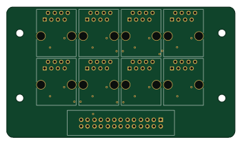
Mesabob
87.5 × 50 mm44 parts2LGPL-3.0979