
Rugrover

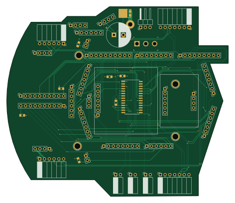
About the Rugrover PCB
Rugrover is an open source AVR/Arduino PCB design by adamgreen, published on GitHub. It is a 4-layer board measuring 117.7 × 100.9 mm, with 46 components from 39 distinct parts.
Its main chip is the Arduino_1pin, from the AVR/Arduino family. Other key parts include the MCP23018-E/SP. By type, the board carries 35 connectors, 6 resistors, 2 capacitors, 1 IC, 1 switch and 1 diode.
It belongs with the dev boards & breakouts, iot & wireless and sensors designs in this gallery.
From the project
A Work In Progress: My modern interpretation of the Rug Warrior Pro
When I first started pursuing robotics as a hobby back in the late 1990s, one of the first books I read was "Mobile Robots: Inspiration to Implementation" by Joseph L. Jones and Anita M. Flynn. I just read it again recently and the core lessons covered by the book are just as useful today as they were back at that time even though some of the technology discussed is now a bit out of date. The mechanical, electrical, motor physics, and behavior based programming topics covered are all still relevant. The Motorola 68HC11 microcontroller and Interactive C programming language are examples of…
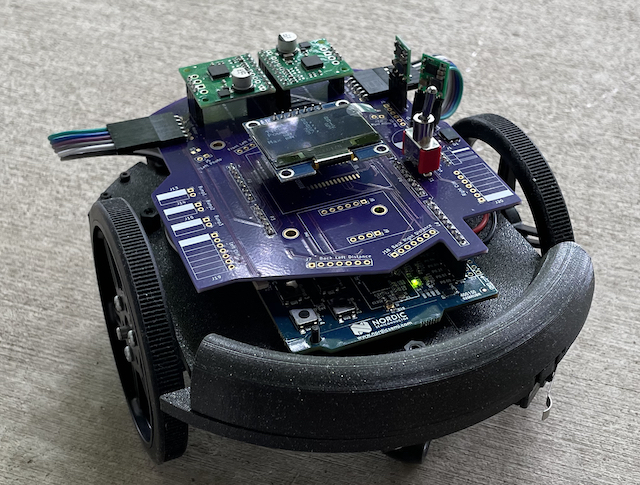
Main components on the Rugrover
Rugrover bill of materials (BOM)
46 components, 39 distinct parts.
| Qty | Part | Footprint | Refs |
|---|---|---|---|
| 1 | MCP23018-E/SP MCP23018 Microchip Technology | SOIC-28W_7.5x17.9mm_P1.27mm | U1 |
| 1 | Battery | PinHeader_1x03_P2.54mm_Horizontal | J1 |
| 1 | 3.3V 500mA Regulator | PinSocket_1x04_P2.54mm_Vertical | J2 |
| 1 | 5.0V 500mA Regulator | PinSocket_1x04_P2.54mm_Vertical | J3 |
| 1 | 12V Boost Regulator | PinSocket_1x06_P2.54mm_Vertical | J4 |
| 1 | Left Photo | PinSocket_1x02_P2.54mm_Vertical | J5 |
| 1 | Front Left Distance | PinSocket_1x07_P2.54mm_Vertical | J6 |
| 1 | Back Left Distance | PinSocket_1x07_P2.54mm_Vertical | J7 |
| 1 | IMU-1 | PinSocket_1x06_P2.54mm_Vertical | J8 |
| 1 | IMU-2 | PinSocket_1x04_P2.54mm_Vertical | J9 |
| 1 | Right Photo Cell | PinSocket_1x02_P2.54mm_Vertical | J10 |
| 1 | Front Center Distance | PinSocket_1x07_P2.54mm_Vertical | J11 |
| 1 | Bump1 | PinSocket_1x02_P2.54mm_Horizontal | J13 |
| 1 | Bump2 | PinSocket_1x02_P2.54mm_Horizontal | J14 |
| 1 | Bump3 | PinSocket_1x02_P2.54mm_Horizontal | J15 |
| 1 | PIR | PinSocket_1x03_P2.54mm_Vertical | J16 |
| 1 | Front Right Distance | PinSocket_1x07_P2.54mm_Vertical | J17 |
| 1 | Back Right Distance | PinSocket_1x07_P2.54mm_Vertical | J18 |
| 1 | Left Cliff | PinSocket_1x07_P2.54mm_Horizontal | J19 |
| 1 | Right Cliff | PinSocket_1x07_P2.54mm_Horizontal | J20 |
Show 19 more
| Qty | Part | Footprint | Refs |
|---|---|---|---|
| 1 | OLED | PinSocket_1x07_P2.54mm_Vertical | J21 |
| 1 | LMotor-1 | PinSocket_1x10_P2.54mm_Vertical | J22 |
| 1 | RMotor-1 | PinSocket_1x10_P2.54mm_Vertical | J23 |
| 1 | LMotor-2 | PinSocket_1x04_P2.54mm_Vertical | J24 |
| 1 | RMotor-2 | PinSocket_1x04_P2.54mm_Vertical | J25 |
| 1 | Left Motor | PinSocket_1x06_P2.54mm_Horizontal | J26 |
| 1 | Right Motor | PinSocket_1x06_P2.54mm_Horizontal | J27 |
| 1 | Power | PinHeader_1x08_P2.54mm_Vertical | P2 |
| 1 | Analog | PinHeader_1x06_P2.54mm_Vertical | P3 |
| 1 | GPIO | PinHeader_1x10_P2.54mm_Vertical | P5 |
| 1 | GPIO | PinHeader_1x08_P2.54mm_Vertical | P6 |
| 1 | GPIO | PinHeader_1x09_P2.54mm_Vertical | P7 |
| 4 | CONN_01X01 | Arduino_1pin | P8, P9, P11, P12 |
| 1 | 100SP1T1B4M2QE Power Switch E-Switch | Toggle_Switch_100SP1T1B4M2QE | S1 |
| 1 | SS10P6-M3/86A | TO-277A | D1 |
| 1 | 2200uF 25V | CP_Radial_D13.0mm_P5.00mm | C1 |
| 1 | 0.1uF | C_0805_2012Metric_Pad1.18x1.45mm_HandSolder | C2 |
| 2 | 1k | R_0805_2012Metric_Pad1.20x1.40mm_HandSolder | R1, R2 |
| 4 | 10k | R_0805_2012Metric_Pad1.20x1.40mm_HandSolder | R3, R4, R5, R6 |
Rugrover design files
The KiCad project lives in the adamgreen/rugrover repository on GitHub; these links point at the commit this page was built from.
- Layouthardware/shield.kicad_pcb
- Schematichardware/shield.kicad_sch
Rugrover: common questions
What microcontroller does the Rugrover use?
The Rugrover is built around the Arduino_1pin, from the AVR/Arduino family.
How big is the Rugrover PCB?
The Rugrover measures 117.7 × 100.9 mm, has 4 copper layers and is 1.769872 mm thick.
How many components are on the Rugrover?
46 components, from 39 distinct parts. The full bill of materials is listed on this page.
Where can I download the Rugrover design files?
From the adamgreen/rugrover repository on GitHub, which has the KiCad layout and the schematic; the links under Design files point to each one.
Can I use the Rugrover design in my own project?
The repository has no license, so all rights stay with adamgreen. Use it as a reference, and ask the author before reusing the design.
Can I test firmware for the Rugrover without the hardware?
Yes. HardLabs builds a simulation of the board from its netlist and BOM, so you can run and debug AVR/Arduino firmware against it before you order a PCB.
Similar boards
 AVR/Arduino
Redox keyboard
mattdibi
162.2 × 126.5 mm77 parts2LMIT2.0k AVR/Arduino
ModuleV450
stuartpittaway
30 × 61.4 mm39 parts2LCC-BY-NC-4.01.1k AVR/Arduino
V4
30 × 50 mm38 parts2LCC-BY-NC-4.01.1k AVR/Arduino
Discipline
coseyfannitutti
304.9 × 122.8 mm170 parts2LCC-BY-NC-4.01.0k AVR/Arduino
Megadesk
gcormier
41.7 × 32.2 mm23 parts2LGPL-3.0818 AVR/Arduino
Easyduino Atmega
Hanqaqa
68.8 × 53.6 mm35 parts4LCERN-OHL-P-2.0746