
Avr door controller

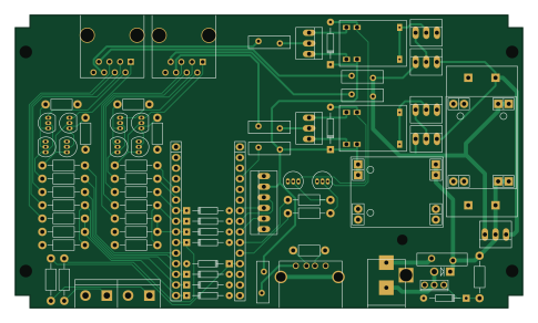
About the Avr door controller PCB
Avr door controller is an open source PCB design by AlbanBedel, published on GitHub. It is a 2-layer board measuring 121 × 70 mm, with 67 components from 25 distinct parts.
Other key parts include the 12V, 5V and 24V. By type, the board carries 24 resistors, 12 diodes, 11 transistors, 8 connectors, 7 fuses and 3 ICs.
From the project
An AVR based door access controller for wiegand readers
This project is about building an open source physical access control system for small communities and groups.
In this directory you will find the hardware design (schematics and PCB) for a two door controller using an Arduino Nano. Its main features are:
Can be powered with 12V or 24V. Support various setup for the door lock, the relay can be connected to 12V, 24V or GND as normally open or as normally closed. An USB power supply to power additional devices such as an AP for network connectivity. Use RJ-45 connectors for the doors to allow standardizing the physical installation.
Main components on the Avr door controller
Avr door controller bill of materials (BOM)
67 components, 25 distinct parts.
| Qty | Part | Footprint | Refs |
|---|---|---|---|
| 1 | 12V | XM1584 | U1 |
| 1 | 5V | XM1584 | U2 |
| 1 | 24V | MT3608 | U3 |
| 10 | Q_NPN_EBC | TO-92_Inline_Narrow_Oval | Q1, Q2, Q3, Q4, Q5, Q6, Q7, Q8 +2 |
| 1 | Q_NMOS_GDS | TO-251AA | Q9 |
| 1 | 24V | BARREL_JACK | CON1 |
| 1 | DOOR1 | RJ45_8 | J1 |
| 1 | DOOR2 | RJ45_8 | J2 |
| 1 | Digital | Socket_Strip_Arduino_1x15 | P1 |
| 1 | Analog | Socket_Strip_Arduino_1x15 | P2 |
| 1 | DOOR1 BTN | bornier2 | P3 |
| 1 | USB_A | USB_A | P6 |
| 1 | DOOR2 BTN | bornier2 | P10 |
| 1 | 3A | Bourns_PPTC_Style_2 | F1 |
| 4 | 0.5A | Bourns_PPTC_Style_1 | F2, F3, F6, F7 |
| 1 | 0.09A | Bourns_PPTC_Style_1 | F4 |
| 1 | 1.6A | Bourns_PPTC_Style_1 | F5 |
| 2 | RELAY | JRC-21F | K1, K2 |
| 1 | TVS | Diode_DO-41_SOD81_Vertical_AnodeUp | D1 |
| 9 | 5.1V | Diode_DO-35_SOD27_Horizontal_RM10 | D2, D3, D6, D7, D8, D9, D12, D13 +1 |
Show 5 more
| Qty | Part | Footprint | Refs |
|---|---|---|---|
| 2 | 1N4148 | Diode_DO-35_SOD27_Horizontal_RM10 | D4, D5 |
| 8 | 1K | Resistor_Horizontal_RM10mm | R1, R4, R5, R6, R7, R10, R11, R12 |
| 4 | 68 | Resistor_Horizontal_RM7mm | R2, R3, R16, R17 |
| 11 | 15K | Resistor_Horizontal_RM10mm | R8, R9, R14, R15, R18, R19, R20, R21 +3 |
| 1 | 150 | Resistor_Horizontal_RM7mm | R13 |
Avr door controller design files
The KiCad project lives in the AlbanBedel/avr-door-controller repository on GitHub; these links point at the commit this page was built from.
Avr door controller: common questions
How big is the Avr door controller PCB?
The Avr door controller measures 121 × 70 mm, has 2 copper layers and is 1.6 mm thick.
How many components are on the Avr door controller?
67 components, from 25 distinct parts. The full bill of materials is listed on this page.
Where can I download the Avr door controller design files?
From the AlbanBedel/avr-door-controller repository on GitHub, which has the KiCad layout; the links under Design files point to each one.
Can I use the Avr door controller design in my own project?
The repository has no license, so all rights stay with AlbanBedel. Use it as a reference, and ask the author before reusing the design.