
Antenna test

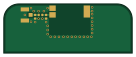
About the Antenna test PCB
Antenna test is an open source PCB design by alvarop, published on GitHub under the MIT license. It is a 4-layer board measuring 34 × 13 mm, with 5 components from 4 distinct parts.
By type, the board carries 2 capacitors, 1 connector, 1 antenna and 1 inductor.
It belongs with the rf & radio designs in this gallery.
From the project
This is a work in progress for a wireless weather station project.
This is a work in progress for a wireless weather station project.
Hardware - Main development board design files Firmware - Code for the microcontroller * Software - Python scripts to communicate with the weather station, log, and plot data
Antenna test bill of materials (BOM)
5 components, 4 distinct parts.
| Qty | Part | Footprint | Refs |
|---|---|---|---|
| 1 | Conn_Coaxial | TE-2337019-1 | J1 |
| 1 | Antenna_Chip | W3211 | AE1 |
| 1 | 0 | L_0402_1005Metric | L1 |
| 2 | DNP | C_0402_1005Metric | C14, C16 |
Antenna test design files
The KiCad project lives in the alvarop/chaac repository on GitHub; these links point at the commit this page was built from.
Antenna test: common questions
How big is the Antenna test PCB?
The Antenna test measures 34 × 13 mm, has 4 copper layers and is 1.6 mm thick.
How many components are on the Antenna test?
5 components, from 4 distinct parts. The full bill of materials is listed on this page.
Where can I download the Antenna test design files?
From the alvarop/chaac repository on GitHub, which has the KiCad layout; the links under Design files point to each one.
Can I use the Antenna test design in my own project?
Yes, under the terms of its MIT license, which alvarop chose for the repository.
More boards in chaac
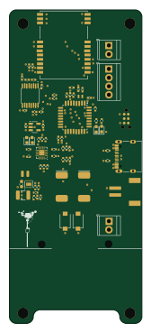 STM32
Chaac ng
39 × 92 mm73 parts4LMIT21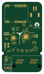 STM32
Chaac
34 × 60 mm67 parts4LMIT21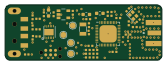 Nordic nRF
NRF52811 USB
41.8 × 14.8 mm42 parts4LMIT21 Nordic nRF
NRF52811 USB LoRa
31 × 19 mm34 parts2LMIT21 Nordic nRF
Rpi nrf52811
26.8 × 14.8 mm28 parts4LMIT21 Nordic nRF
Chaac Radio
40 × 20 mm21 parts4LMIT21
Xbee Rpi Hat
25.4 × 22.9 mm6 parts2LMIT21
Similar boards
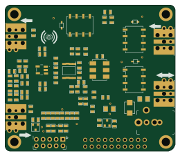
Hat
pa3gsb
65 × 56 mm81 parts2LNo license675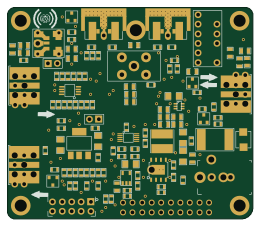
Radioberry preamp
65 × 56 mm137 parts2LNo license675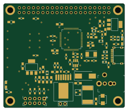
Radioberry juice
65 × 56 mm87 parts2LNo license675
Goodwatch20
travisgoodspeed
25.6 × 27.6 mm20 parts2LNo license568
GoodPocketWatch
75.2 × 101.2 mm56 parts2LNo license568
Goodwatch31
25.6 × 27.6 mm23 parts2LNo license568