
Pulse-Generator

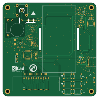
About the Pulse-Generator PCB
Pulse-Generator is an open source STM32 PCB design by AnalogDragon, published on GitHub under the Custom license license. It is a 2-layer board measuring 98 × 98 mm, with 90 components from 35 distinct parts.
Its main chip is the STM32G030C8Tx, from the STM32 family. Other key parts include the TLV9061IDBVR, SGM3204 and TX4310B. By type, the board carries 36 resistors, 31 capacitors, 7 switches, 5 ICs, 4 connectors and 4 diodes.
It belongs with the test & measurement, displays & leds and power & battery designs in this gallery.
From the project
Pulse generator for test Geiger counters and dosimetry instruments.
Used for testing and calibrating dose rate instruments such as survey meters or calibrators. STM32G0, KiCad.
This device was built because I purchased a LUDLUM Model 3 and a Model 2360, both of which require calibration of multiple threshold levels, so I made this small tool for that purpose.
Functions: - 1. Generates adjustable pulses with amplitude 2 mV–1000 mV, pulse width 50 nS–500 µS, adjustable frequency, and selectable positive/negative polarity, for calibration or performance verification; - 2. Multiple operating modes; - 3. Output interface changed to MHV connector (previous…
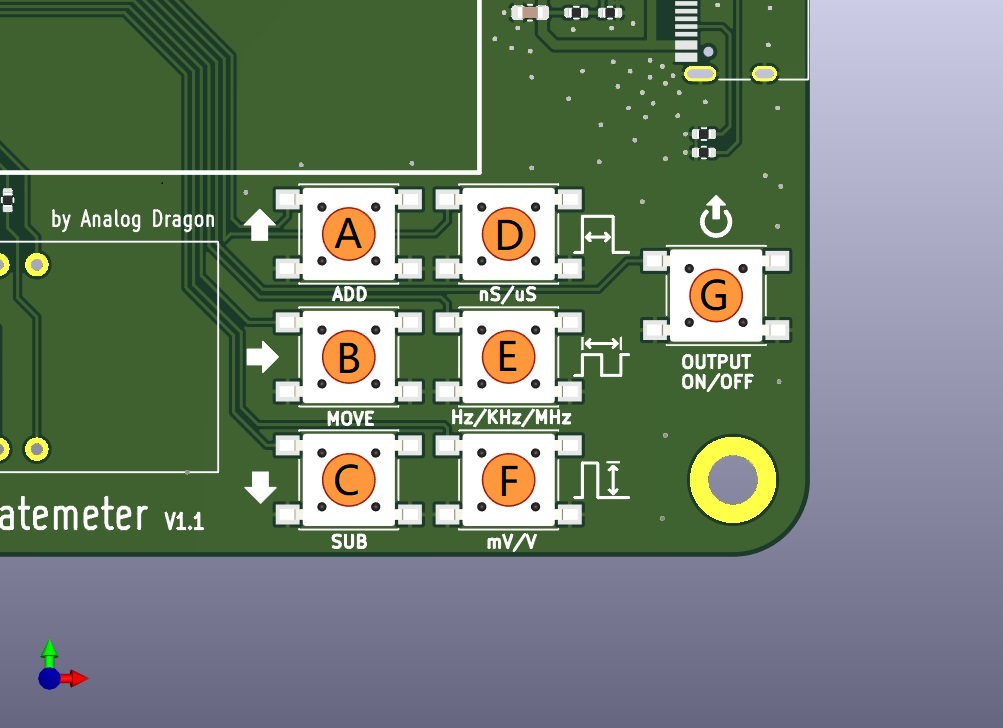
Main components on the Pulse-Generator
Pulse-Generator bill of materials (BOM)
90 components, 35 distinct parts.
| Qty | Part | Footprint | Refs |
|---|---|---|---|
| 2 | TLV9061IDBVR | SOT-23-5 | U1, U2 |
| 1 | SGM3204 | SOT-23-6 | U3 |
| 1 | TX4310B | SOT-23-6 | U4 |
| 1 | STM32G030C8Tx | LQFP-48_7x7mm_P0.5mm | U5 |
| 1 | AO3401A | SOT-23 | Q1 |
| 1 | FDG6301N | SOT-363_SC-70-6 | Q3 |
| 1 | MHV-KE | BNC_TEConnectivity_1478204_Vertical | J1 |
| 1 | USB_C_Receptacle_USB2.0 | USB_C_Receptacle_HRO_TYPE-C-31-M-12 | J2 |
| 1 | Conn_01x02 | JST_PH_S2B-PH-SM4-TB_1x02-1MP_P2.00mm_Horizontal | J3 |
| 1 | Conn_01x04 | PinSocket_1x04_P2.54mm_Vertical | J4 |
| 7 | 6*6*5 100g | SW_SPST_PTS645 | SW1, SW2, SW3, SW4, SW5, SW6, SW7 |
| 1 | SMBJ3.3A | D_SMB | D1 |
| 1 | 1N4007 | D_SOD-323_HandSoldering | D2 |
| 1 | display-led-0.39in-6dig | display-led-0.39in-6dig | D3 |
| 1 | B5819W | D_SOD-123 | D5 |
| 1 | 600R/100M | L_0603_1608Metric | FB1 |
| 1 | 10nF/4kV | C_Rect_L13.5mm_W4.0mm_P10.00mm_FKS3_FKP3_MKS4 | C1 |
| 7 | 105/25V | C_0402_1005Metric | C2, C4, C5, C8, C18, C19, C24 |
| 10 | 104/50V | C_0402_1005Metric | C3, C11, C13, C15, C17, C22, C23, C25 +2 |
| 2 | 475/10V | C_0603_1608Metric | C6, C9 |
Show 15 more
| Qty | Part | Footprint | Refs |
|---|---|---|---|
| 6 | 106/16V | C_0603_1608Metric | C7, C10, C12, C14, C26, C27 |
| 1 | 226/6.3V | C_0603_1608Metric | C16 |
| 2 | 101/50V | C_0402_1005Metric | C20, C21 |
| 2 | 103/50V | C_0402_1005Metric | C30, C31 |
| 1 | 100R | R_Axial_DIN0411_L9.9mm_D3.6mm_P15.24mm_Horizontal | R1 |
| 2 | 500M | R_1206_3216Metric | R2, R3 |
| 1 | 1M | R_0603_1608Metric | R4 |
| 4 | 10K | R_0402_1005Metric | R5, R6, R15, R33 |
| 5 | 100R | R_0402_1005Metric | R7, R8, R9, R14, R37 |
| 2 | 1R | R_0402_1005Metric | R10, R12 |
| 1 | 22K | R_0402_1005Metric | R11 |
| 15 | 330R | R_0402_1005Metric | R16, R17, R18, R19, R20, R21, R22, R23 +7 |
| 1 | 1K | R_0402_1005Metric | R31 |
| 2 | 200K | R_0402_1005Metric | R32, R36 |
| 2 | 5.1K | R_0402_1005Metric | R34, R35 |
Pulse-Generator design files
The KiCad project lives in the AnalogDragon/Pulse-Generator repository on GitHub; these links point at the commit this page was built from.
- LayoutHW_pulsecal/pulsecal.kicad_pcb
- SchematicHW_pulsecal/pulsecal.kicad_sch
Pulse-Generator: common questions
What microcontroller does the Pulse-Generator use?
The Pulse-Generator is built around the STM32G030C8Tx, from the STM32 family.
How big is the Pulse-Generator PCB?
The Pulse-Generator measures 98 × 98 mm, has 2 copper layers and is 1.6 mm thick.
How many components are on the Pulse-Generator?
90 components, from 35 distinct parts. The full bill of materials is listed on this page.
Where can I download the Pulse-Generator design files?
From the AnalogDragon/Pulse-Generator repository on GitHub, which has the KiCad layout and the schematic; the links under Design files point to each one.
Can I use the Pulse-Generator design in my own project?
It is published under Custom license, which limits how it may be reused; read the license before building on it.
Can I test firmware for the Pulse-Generator without the hardware?
Yes. HardLabs builds a simulation of the board from its netlist and BOM, so you can run and debug STM32 firmware against it before you order a PCB.
Similar boards
 STM32
LumenPnP Motherboard
opulo-inc
149 × 95 mm296 parts4LCC-BY-SA-4.03.7k STM32
Base
google
52.3 × 52.3 mm36 parts2LApache-2.02.9k STM32
Main panel
234 × 84 mm26 parts4LApache-2.02.9k STM32
Type g
169 × 30 mm24 parts2LApache-2.02.9k STM32
Type a
150 × 30 mm14 parts2LApache-2.02.9k STM32
Type c
188 × 30 mm17 parts2LApache-2.02.9k