
RoverSpine

About the RoverSpine PCB
RoverSpine is an open source PCB design by AndyChen227, published on GitHub under the Custom license license. It is a board, with 14 components from 4 distinct parts.
By type, the board carries 12 resistors and 2 connectors.
It belongs with the robotics & motion designs in this gallery.
From the project
Custom electronics for RoverPi, designed from zero PCB experience. The Pi is the brain; this is the spine — where the reflexes live. 为 RoverPi 自制的电路板,从零基础开始。
Replaces the ten loose dupont control wires between the Raspberry Pi 5 and the WHEELTEC D50A motor driver with one small passive board and two ribbon cables.
[ ] Rev A — schematic complete, footprints not assigned.
Three-state notation, same as the rest of the project: [x] met its exit criteria on the rover · [~] exists and powers up · [ ] pending. Never [x] because the schematic looks right.
RoverSpine bill of materials (BOM)
14 components, 4 distinct parts.
| Qty | Part | Footprint | Refs |
|---|---|---|---|
| 1 | RPI_GPIO_2x20 | J1 | |
| 1 | D50A_CONTROL_2x5 | J2 | |
| 6 | 33 | R1, R2, R3, R4, R5, R6 | |
| 6 | 10k | R7, R8, R9, R10, R11, R12 |
RoverSpine design files
The KiCad project lives in the AndyChen227/RoverSpine repository on GitHub; these links point at the commit this page was built from.
RoverSpine: common questions
How many components are on the RoverSpine?
14 components, from 4 distinct parts. The full bill of materials is listed on this page.
Where can I download the RoverSpine design files?
From the AndyChen227/RoverSpine repository on GitHub, which has the schematic; the links under Design files point to each one.
Can I use the RoverSpine design in my own project?
It is published under Custom license, which limits how it may be reused; read the license before building on it.
Similar boards

Stack chan
stack-chan
50 × 50 mm33 parts2LApache-2.01.7k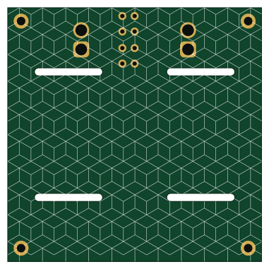
Cube batteryboard
willem-pennings
95 × 95 mm4 parts2LGPL-3.01.1k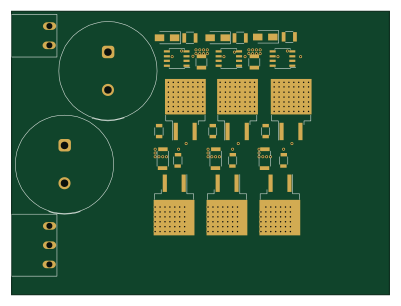
Trollerv2
rene-dev
100 × 75 mm33 parts4LGPL-3.0979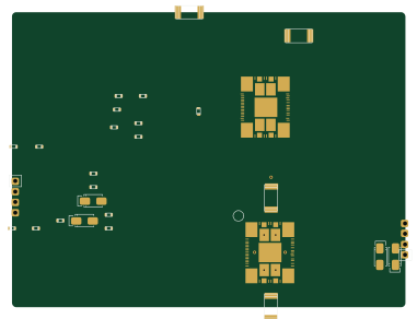
Powerstep
95.2 × 71.5 mm28 parts4LGPL-3.0979
11ua
57.3 × 19 mm26 parts2LGPL-3.0979
Diff driver
32 × 22 mm14 parts2LGPL-3.0979