
Radio

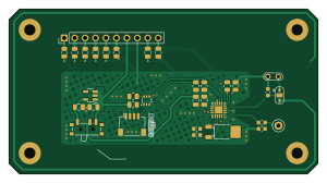
About the Radio PCB
Radio is an open source PCB design by ansemjo, published on GitHub under the CERN-OHL-P-2.0 license. It is a 2-layer board measuring 75 × 40 mm, with 32 components from 27 distinct parts.
Other key parts include the AP2114H-3.3TRG1 and SN74HCT245PWR. By type, the board carries 12 resistors, 9 capacitors, 2 ICs, 2 connectors, 2 antennas and 2 inductors.
It belongs with the displays & leds and rf & radio designs in this gallery.
From the project
hardware project for a clock around a russian ivl2-5/7 vfd and an esp32-wroom module
A vacuum-flourescent display (VFD) clock project based on Soviet NOS IVL2-7/5 / ИВЛ2-7/5 tubes. This has been my first somewhat complex hardware project when I got into electronics design in 2020 and grew to multiple iterations over the years.
vfddriver — updated display board, which can be used over I2C sandwich — the original clock design with two boards * other — links to initial research prototypes and various experiments
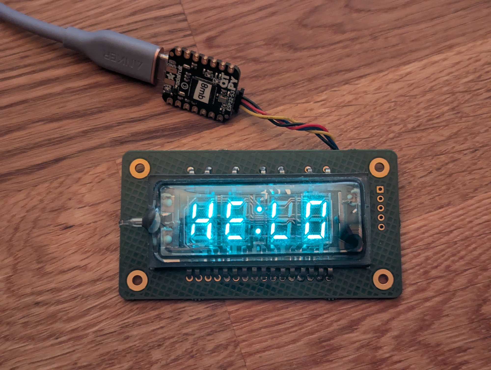
Main components on the Radio
Radio bill of materials (BOM)
32 components, 27 distinct parts — part numbers from the project's BOM.
| Qty | Part | Footprint | Refs |
|---|---|---|---|
| 1 | AP2114H-3.3TRG1 Si4706-D50-GM Diodes Inc. | SiliconLabs_QFN-20-1EP_3x3mm_P0.5mm_EP1.8x1.8mm | U1 |
| 1 | SN74HCT245PWR MIC5504-3.3YM5 Texas Instruments | SOT-23-5 | U2 |
| 1 | MBT3904DW1T1G BSD840NH6327XTSA1 ON Semiconductor | SOT-363_SC-70-6 | Q1 |
| 1 | ECS-.327-12.5-13FLX-C 32.786kHz ECS Inc. | Crystal_SMD_MicroCrystal_MS1V-T1K | Y1 |
| 1 | PPTC081LFBN-RC Header Sullins | PinHeader_1x10_P2.54mm_Vertical | J1 |
| 1 | PRPC040DAAN-RC I2C Sullins | JST_SH_SM04B-SRSS-TB_1x04-1MP_P1.00mm_Horizontal | J2 |
| 1 | Wire Antenna | TestPoint_Loop_D2.50mm_Drill1.0mm | AE1 |
| 1 | Wire Loop Antenna | TestPoint_2Pads_Pitch2.54mm_Drill0.8mm | AE2 |
| 1 | CKN12221-1 Voltage Selector C&K | SW_SPDT_PCM12 | SW1 |
| 1 | BLM21PG221SZ1D 75Ω Murata | L_0603_1608Metric | FB1 |
| 1 | 120nH | L_0603_1608Metric | L1 |
| 1 | CL21A475KAQNNNE 10nF Samsung | C_0805_2012Metric | C1 |
| 1 | CL21A475KAQNNNE 22pF Samsung | C_0603_1608Metric | C2 |
| 1 | CL21B102KBANNNC 22pF Samsung | C_0603_1608Metric | C3 |
| 1 | CL21B104KACNNNC 100nF Samsung | C_0805_2012Metric | C4 |
| 1 | CL21A106KOQNNNE 1µF Samsung | C_0805_2012Metric | C5 |
| 1 | CL21B105KAFNNNG 1µF Samsung | C_0805_2012Metric | C6 |
| 2 | CL21B104KACNNNC 1µF Samsung | C_0805_2012Metric | C7, C8 |
| 1 | CL21B104KACNNNC 4.7pF Samsung | C_0603_1608Metric | C9 |
| 1 | RC0805FR-071ML 10kΩ Yageo | R_0805_2012Metric | R1 |
Show 7 more
| Qty | Part | Footprint | Refs |
|---|---|---|---|
| 1 | RC0805FR-0710KL 10kΩ Yageo | R_0805_2012Metric | R2 |
| 1 | RC0805FR-0710KL 330Ω Yageo | R_0805_2012Metric | R3 |
| 1 | RC0805FR-072K2L 330Ω Yageo | R_0805_2012Metric | R4 |
| 3 | RC0805FR-074K7L 330Ω Yageo | R_0805_2012Metric | R5, R6, R8 |
| 1 | RC0805FR-071KL 330Ω Yageo | R_0805_2012Metric | R7 |
| 2 | RC0805FR-0710KL 4.7kΩ Yageo | R_0805_2012Metric | R9, R10 |
| 2 | RC0805JR-075K1L 4.7kΩ Yageo | R_0805_2012Metric | R11, R12 |
Radio design files
The KiCad project lives in the ansemjo/chronovfd repository on GitHub; these links point at the commit this page was built from.
Radio: common questions
How big is the Radio PCB?
The Radio measures 75 × 40 mm, has 2 copper layers and is 1.6002 mm thick.
How many components are on the Radio?
32 components, from 27 distinct parts, with part numbers taken from the project's own BOM. The full bill of materials is listed on this page.
Where can I download the Radio design files?
From the ansemjo/chronovfd repository on GitHub, which has the KiCad layout, the schematic and the BOM; the links under Design files point to each one.
Can I use the Radio design in my own project?
Yes, under the terms of its CERN-OHL-P-2.0 license, which ansemjo chose for the repository.
More boards in chronovfd
 ESP32
Clockcore
75 × 40 mm54 parts2LCERN-OHL-P-2.012 ESP32
Radiocore
75 × 40 mm46 parts2LCERN-OHL-P-2.012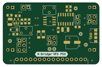
Breadboard VFD PSU
51.7 × 33 mm39 parts2LCERN-OHL-P-2.012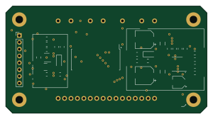
Vfddriver
75 × 40 mm32 partsCERN-OHL-P-2.012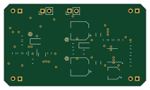
Universal vfd psu
53 × 30.5 mm28 partsCERN-OHL-P-2.012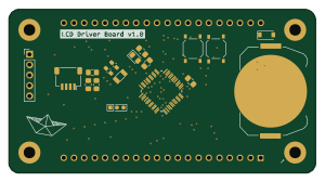
LCD Driver Board
75 × 40 mm20 parts2LCERN-OHL-P-2.012
Similar boards
View screen
scottbez1
35 × 35 mm12 parts2LApache-2.022.2k
LevelShifterBreakout
15.2 × 20.3 mm5 parts2LApache-2.022.2k
View base
81.2 × 81.2 mm81 parts2LApache-2.022.2k
BM28B0.6-24DSBreakout
15.2 × 35.6 mm3 parts2LApache-2.022.2k
Display eval
byrantech
52.1 × 22.6 mm12 parts4LMIT4.3k
ChainlinkDriverTester
198.1 × 95.3 mm123 parts2LApache-2.04.2k