
LATCH

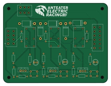
About the LATCH PCB
LATCH is an open source PCB design by Anteater-Electric-Racing, published on GitHub. It is a 2-layer board measuring 105.8 × 80.8 mm, with 35 components from 12 distinct parts.
By type, the board carries 15 resistors, 8 diodes, 3 transistors, 3 connectors, 3 relays and 3 switches.
LATCH bill of materials (BOM)
35 components, 12 distinct parts — part numbers from the project's BOM.
| Qty | Part | Footprint | Refs |
|---|---|---|---|
| 3 | IRF9540 PMOS IRF9540 Vishay / Siliconix | TO-220-3_Vertical | Q1, Q2, Q3 |
| 1 | 39281123 Molex | MOLEX_39281123 | J1 |
| 1 | 39281083 Molex | MOLEX_39281083 | J4 |
| 1 | 39281063 Molex | MOLEX_39281063 | J5 |
| 3 | G6B-2214P-US DC12 Omron Electronics | RELAY_G6B-2114P-US_OMR | K1, K2, K4 |
| 3 | B3F-1000 SW_Push Omron Electronics Inc | SW_PUSH_6mm | SW1, SW2, SW3 |
| 5 | SB560-3G Diotec Semiconductor | D_DO-201_P15.24mm_Horizontal | D1, D2, D3, D7, D8 |
| 3 | WP7113ID DEBUG LED Kingbright | LED_D5.0mm | D4, D5, D6 |
| 6 | CF14JT1K00 1k Stackpole Electronics | R_Axial_DIN0207_L6.3mm_D2.5mm_P10.16mm_Horizontal | R1, R2, R3, R6, R8, R11 |
| 3 | CF14JT470R 470 Stackpole Electronics | R_Axial_DIN0207_L6.3mm_D2.5mm_P10.16mm_Horizontal | R4, R7, R9 |
| 3 | CF14JT10K0 10k Stackpole Electronics | R_Axial_DIN0207_L6.3mm_D2.5mm_P10.16mm_Horizontal | R5, R10, R12 |
| 3 | CD14ZT0R00 0 Stackpole Electronics | R_Axial_DIN0207_L6.3mm_D2.5mm_P10.16mm_Horizontal | R13, R14, R15 |
LATCH design files
The KiCad project lives in the Anteater-Electric-Racing/electrical-pcbs repository on GitHub; these links point at the commit this page was built from.
LATCH: common questions
How big is the LATCH PCB?
The LATCH measures 105.8 × 80.8 mm, has 2 copper layers and is 1.6 mm thick.
How many components are on the LATCH?
35 components, from 12 distinct parts, with part numbers taken from the project's own BOM. The full bill of materials is listed on this page.
Where can I download the LATCH design files?
From the Anteater-Electric-Racing/electrical-pcbs repository on GitHub, which has the KiCad layout, the schematic and the BOM; the links under Design files point to each one.
Can I use the LATCH design in my own project?
The repository has no license, so all rights stay with Anteater-Electric-Racing. Use it as a reference, and ask the author before reusing the design.
More boards in electrical-pcbs
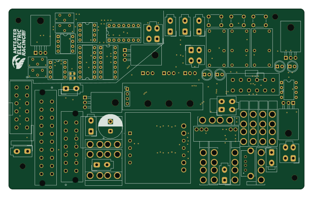
SafetyBoard
154 × 93.9 mm166 parts4LNo license0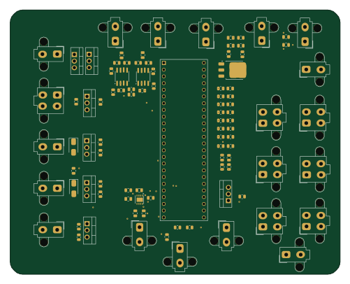 NXP
NXPCcm
125 × 100 mm96 parts2LNo license0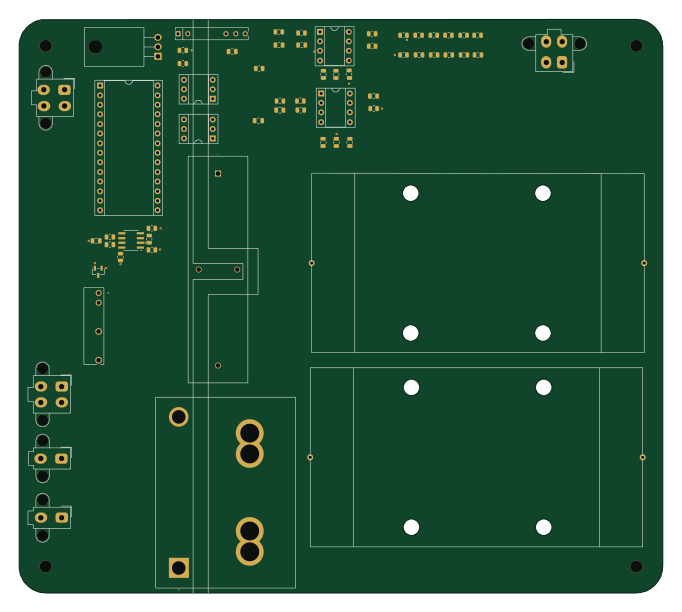
Pcc v0.1
170.3 × 151.7 mm61 parts2LNo license0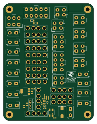
PowerDistributionBoard
76.9 × 99.8 mm58 parts2LNo license0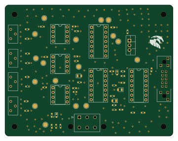
BSPD
90 × 70 mm54 parts2LNo license0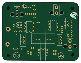
RTM
71 × 54.8 mm41 parts2LNo license0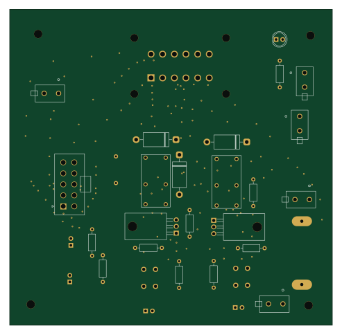
ChargeBoardMaster
123 × 120.7 mm36 parts2LNo license0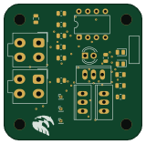
TSSI
40 × 39.5 mm22 parts2LNo license0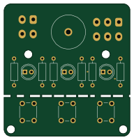
Hi board bbc1
47.8 × 50.3 mm15 parts2LNo license0