
Lead-Compensator

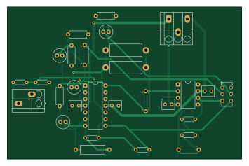
About the Lead-Compensator PCB
Lead-Compensator is an open source PCB design by ardagurbuuz, published on GitHub. It is a 2-layer board measuring 88.5 × 57.5 mm, with 29 components from 15 distinct parts.
Other key parts include the TL074 and TL071. By type, the board carries 15 resistors, 4 capacitors, 2 ICs and 1 switch.
From the project
Analog lead compensator for a second-order plant to improve transient performance (reduced overshoot, faster settling).
This repository documents an end-to-end control + hardware workflow: designing a lead compensator, validating it at model-level (MATLAB/Simulink) and circuit-level (SPICE tools), and implementing it as an op-amp analog controller on a KiCad PCB.
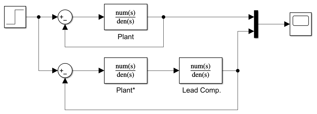
A benchmark plant model is used as the baseline system:
1. Uncompensated loop: plant-only closed-loop response 2. Compensated loop: plant + lead compensator closed-loop response
Main components on the Lead-Compensator
Lead-Compensator bill of materials (BOM)
29 components, 15 distinct parts.
| Qty | Part | Footprint | Refs |
|---|---|---|---|
| 1 | TL074 | DIP-14_W7.62mm | U1 |
| 1 | TL071 | DIP-8_W7.62mm | U2 |
| 4 | 100n | C_Rect_L4.6mm_W3.8mm_P2.50mm_MKS02_FKP02 | CDCP5, CDCP6, CDCP7, CDCP8 |
| 1 | Conn_01x02 | TerminalBlock_Degson_DG250-3.5-02P_1x02_P3.50mm_45Degree | J_IN1 |
| 1 | Conn_01x03 | TerminalBlock_Degson_DG250-3.5-03P_1x03_P3.50mm_45Degree | J_PWR2 |
| 1 | 10M | R_Axial_DIN0309_L9.0mm_D3.2mm_P12.70mm_Horizontal | RLK16 |
| 1 | SW_Slide_DPDT | SW_CK_JS202011AQN_DPDT_Angled | SW1 |
| 2 | 10u | C_Radial_D5.0mm_H11.0mm_P2.00mm | C1, C2 |
| 2 | 1u | C_Radial_D5.0mm_H11.0mm_P2.00mm | C3, C4 |
| 5 | 100k | R_Axial_DIN0207_L6.3mm_D2.5mm_P7.62mm_Horizontal | R1, R2, R3, R4, R13 |
| 4 | 10k | R_Axial_DIN0204_L3.6mm_D1.6mm_P5.08mm_Horizontal | R5, R6, R7, R8 |
| 1 | 560k | R_Axial_DIN0207_L6.3mm_D2.5mm_P7.62mm_Horizontal | R9 |
| 2 | 330k | R_Axial_DIN0414_L11.9mm_D4.5mm_P15.24mm_Horizontal | R10, R11 |
| 1 | 33k | R_Axial_DIN0207_L6.3mm_D2.5mm_P7.62mm_Horizontal | R12 |
| 2 | 1k | R_Axial_DIN0204_L3.6mm_D1.6mm_P5.08mm_Horizontal | R14, R15 |
Lead-Compensator design files
The KiCad project lives in the ardagurbuuz/Lead-Compensator repository on GitHub; these links point at the commit this page was built from.
Lead-Compensator: common questions
How big is the Lead-Compensator PCB?
The Lead-Compensator measures 88.5 × 57.5 mm, has 2 copper layers and is 1.6 mm thick.
How many components are on the Lead-Compensator?
29 components, from 15 distinct parts. The full bill of materials is listed on this page.
Where can I download the Lead-Compensator design files?
From the ardagurbuuz/Lead-Compensator repository on GitHub, which has the KiCad layout and the schematic; the links under Design files point to each one.
Can I use the Lead-Compensator design in my own project?
The repository has no license, so all rights stay with ardagurbuuz. Use it as a reference, and ask the author before reusing the design.