
53 open source boards using the TL071
Real designs built with the TL071, from public GitHub projects: a quick way to see how others power, decouple and connect it. Each board comes with its KiCad files, full parts list and a render — and you can simulate its firmware on HardLabs.
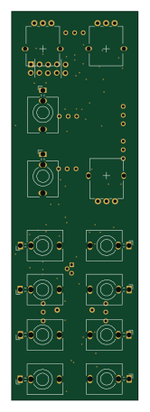
VCO
nickajeglin
37 × 113.9 mm104 parts2LNo license208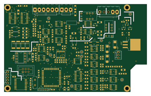 AVR/Arduino
Smu main 1
jaromir-sukuba
130 × 80 mm206 parts2LNo license188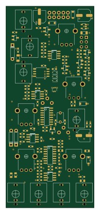 AVR/Arduino
Foundation
odeliy
48 × 110 mm123 parts2LNo license37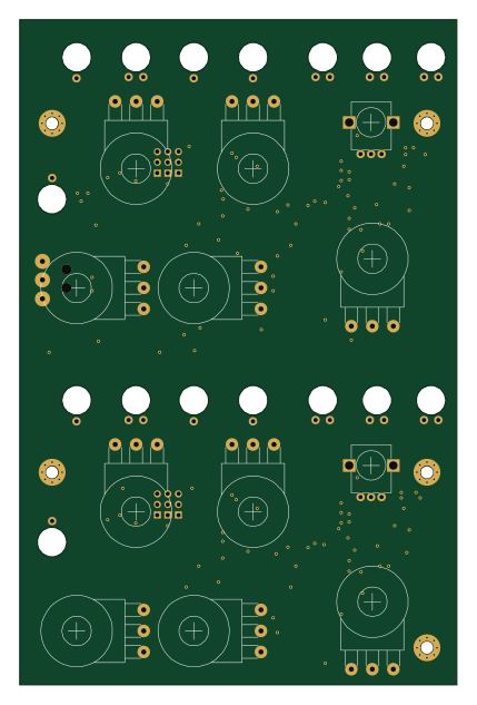
258D
DunningtonAudio
104 × 158 mm219 parts2LGPL-3.031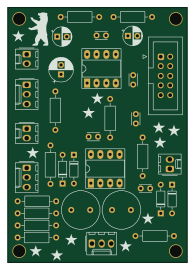
Microphone preamp
polykit
47.5 × 67.5 mm34 parts2LNo license15- schematic only · 99 partsSTM32
Midimagic
herculesxe5
99 partsLGPL-3.014 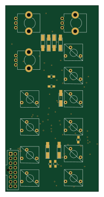
MFOSmod
Micosilent
50 × 100 mm102 parts2LCC-BY-NC-4.013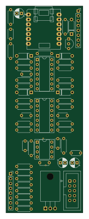 Renesas
Bing bong pcb audio
GlobalSequence
40.3 × 108 mm55 parts2LNo license11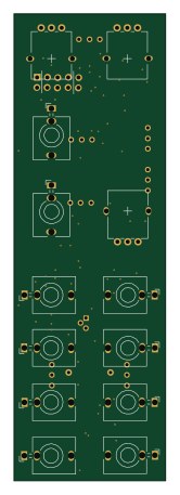
VCO
VincentPeters
37 × 113.9 mm104 parts2LNo license9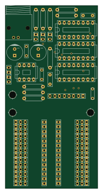
Matcher
elektrouwe
49.5 × 98 mm84 parts2LCC0-1.07- schematic only · 10 partsAVR/Arduino
Korg ms20m extra midi2cv
retango
10 partsGPL-3.07 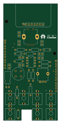
Dat ting Module
Len42
50.5 × 108.5 mm76 parts2LNo license4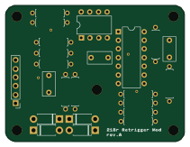
218r Retrigger Mod
triglav-modular
52.6 × 39.9 mm23 parts2LUnlicense4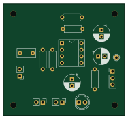
CursoKicad CircularFab2022 2
SmartOpenLab
47 × 43.2 mm16 parts2LNo license4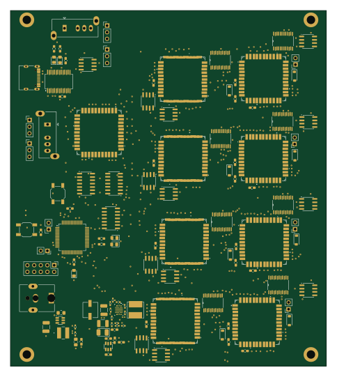 STM32
MainBoard
hughe349
120 × 135 mm139 parts4LGPL-3.02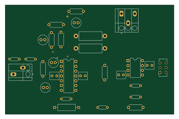
Lead-Compensator
ardagurbuuz
88.5 × 57.5 mm29 parts2LNo license2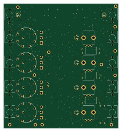
Twangilizer
shannon-greenlight
101.3 × 110 mm454 parts4LNo license1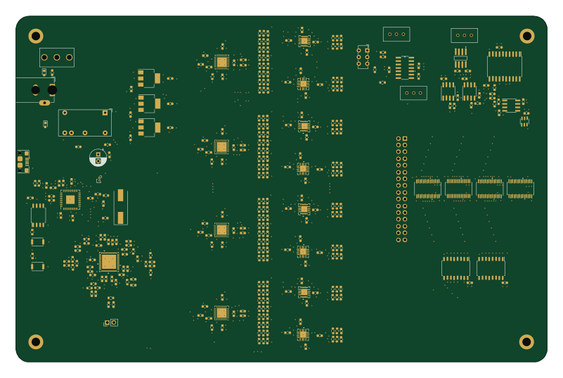 RP2040/RP2350
EIT-Machine
Alberta2514640
200 × 130 mm356 parts4LNo license1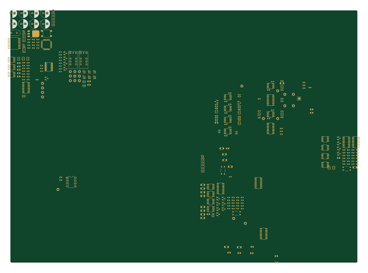 STM32
A1 - Analogue Board
DumberThanUsual
309.1 × 225.1 mm273 parts2LNo license1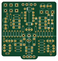
Bd-2
devilmollusk
50 × 52.8 mm65 parts2LNo license1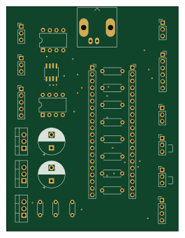 STM32
Function-Generator
MUDAL
65 × 85 mm30 parts2LGPL-3.01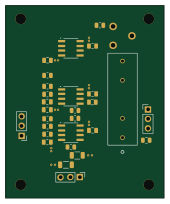
EFNMR transmit amp board
marekpechal
42 × 51 mm29 parts2LNo license1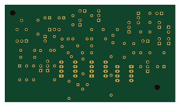
Flipped
carebare47
92.5 × 52.8 mm47 parts2LGPL-3.00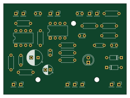
Ring modulator
abrugsch
63.5 × 47 mm38 parts2LUnlicense0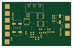
Pulsometer
Matii178
63.3 × 40.4 mm31 parts2LNo license0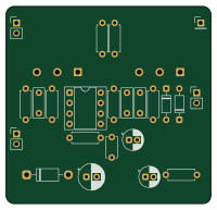
Diy distortion pedal
maui-i
50 × 48 mm25 parts2LMIT0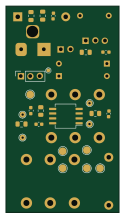
Amp distortion
Skelebot
29.8 × 54.6 mm23 parts2LGPL-3.00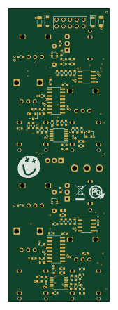 AVR/Arduino
Paradox
38 × 110 mm114 parts2LNo license37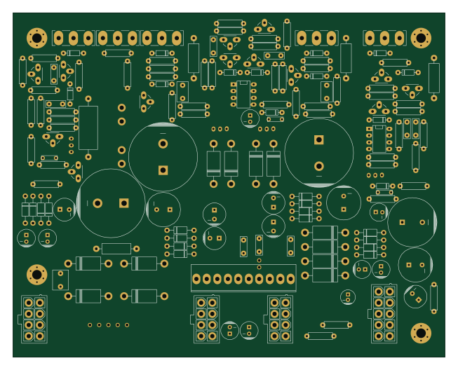
Power supply
romavis
163 × 130 mm168 parts2LCC-BY-SA-4.07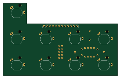
DMH VCO 40106 PCB Conn Mk2
DeMarco
98 × 62 mm17 parts2LNo license5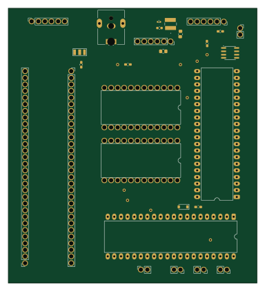
SignleCellBoard
95.3 × 105.4 mm37 parts2LGPL-3.02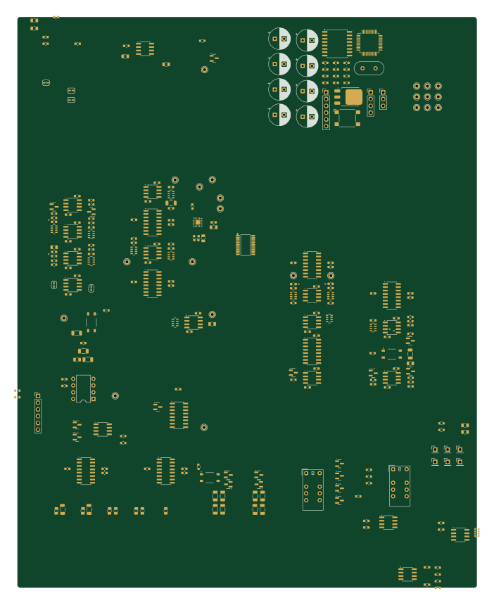 STM32
DSMU A1
172.8 × 214.7 mm272 parts2LNo license1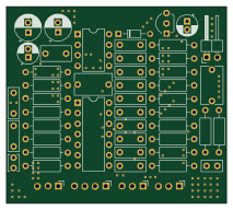
Distortion
Network-Direction
53.3 × 47.5 mm50 parts2LNo license0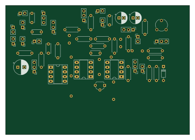
Vca--autosaaved
99.1 × 69.9 mm47 parts2LGPL-3.00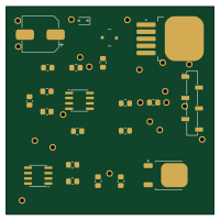
Voltage Regulator seneryo Y (Input 15V)
manyetox
50 × 50 mm22 parts2LNo license0- schematic only · 12 parts
Cv output
carr-james
12 parts2LNo license0
How designs wire the TL071
Read from the KiCad layouts of 36 open source designs, one per repository: what each pin of the TL071 connects to, and the resistors, capacitors and other passives placed on it.
- The NULL pins is left unconnected on 89% of them (GND on 2, a signal on 5).
- The - pin has a series resistor on 26 of 36 designs, most often 100 kΩ (then 10 kΩ).
- The OUT pin has a series resistor on 23 of 33 designs, most often 1 kΩ (then 4.7 kΩ).
- The V- pin has a decoupling capacitor on 15 of 36 designs, most often 100 nF (then 470 µF).
| Pin | Connected to | Parts on the pin |
|---|---|---|
| NULLpin 1, 5 | Connected to: Not connected 89% | — |
| -pin 2 | Connected to: Signal 94% |
|
| +pin 3 | Connected to: Signal 72% · GND 28% |
|
| V-pin 4 | Connected to: -12V 58% · GND 28% |
|
| OUTpin 6 | Connected to: Signal 94% |
|
| V+pin 7 | Connected to: 12V 88% |
|
| NCpin 8 | Connected to: Not connected 97% | — |
Connections count pins, parts count designs; values in brackets are how many parts had that value. Designs read include VCO by nickajeglin, Smu main 1 by jaromir-sukuba, 3xVCA by odeliy and 258D by DunningtonAudio.
The TL071 in open source designs
The gallery holds 53 open source boards using the TL071 from 39 GitHub repositories; a typical one measures about 74.3 × 85 mm and carries around 72 components.
82% are two-layer designs, the rest use four layers or more, and 36% carry an open source license.
The most starred is VCO by nickajeglin.
Parts used alongside the TL071
Microcontrollers on boards using the TL071
What boards using the TL071 are built for
TL071: common questions
Where can I find a TL071 reference design?
Each of the 53 boards on this page is a real design using the TL071. Open one to see how it is wired up, with the full BOM, a render of the layout and links to its KiCad files.
How is the TL071 NULL pin connected?
The NULL pins is left unconnected on 89% of them (GND on 2, a signal on 5). Counted from the KiCad layouts of 36 open source designs using the TL071.
What resistor goes on the TL071 - pin?
The - pin has a series resistor on 26 of 36 designs, most often 100 kΩ (then 10 kΩ). Counted from the KiCad layouts of 36 open source designs using the TL071.
What resistor goes on the TL071 OUT pin?
The OUT pin has a series resistor on 23 of 33 designs, most often 1 kΩ (then 4.7 kΩ). Counted from the KiCad layouts of 36 open source designs using the TL071.
What parts are used alongside the TL071?
The TL074, TL072, LM13700, OP275 and ISO7341c appear in the most repositories here.
Which microcontrollers do boards using the TL071 use?
Most are built on AVR/Arduino (6), STM32 (6), Renesas (1) and RP2040/RP2350 (1).
How big is a typical board using the TL071?
The median is 74.3 × 85 mm, and 82% are two-layer designs.
What is the most popular open source board using the TL071?
By GitHub stars, VCO by nickajeglin, with 208 stars.
Can I simulate one of these boards using the TL071 before building it?
Yes. HardLabs turns a board's netlist and BOM into a working simulation, so you can boot and test firmware against it with no hardware on your desk.