
Adc test board

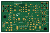
About the Adc test board
Adc test board is an open source PCB design by auselia, published on GitHub. It is a 2-layer board measuring 50 × 32 mm, with 67 components from 29 distinct parts.
Other key parts include the OPA2365, THS4531, ADS7057, XC6206P332MR-G and LM393. By type, the board carries 29 capacitors, 25 resistors, 7 ICs, 4 connectors and 1 diode.
From the project
ADS7057 test board: perfboard SMA -> filters -> ADC + wake comparator -> ZedBoard PMOD (KiCad 10, JLCPCB-ready)
The middle step between the perfboard and the AFE PCB. It takes the perfboard charge-amplifier output on an SMA connector, filters it, digitizes it with the ADS7057, and gives the SPI bus and a wake-up line to a ZedBoard PMOD port.
The topology is the one in the AFE v0.1 design description, rebuilt around JLCPCB Basic parts. Only the ADS7057, the OPA2365 and the THS4531 pay the $3.07 extended-part fee.
Main components on the Adc test board
Adc test board bill of materials (BOM)
67 components, 29 distinct parts — part numbers from the project's BOM.
| Qty | Part | Footprint | Refs |
|---|---|---|---|
| 2 | OPA2365 | SOIC-8_3.9x4.9mm_P1.27mm | U1, U2 |
| 1 | THS4531 | SOIC-8_3.9x4.9mm_P1.27mm | U3 |
| 1 | ADS7057 | ADS7057_X2QFN-8_1.5x1.5mm | U4 |
| 1 | XC6206P332MR-G | SOT-23 | U5 |
| 1 | LM393 | SOIC-8_3.9x4.9mm_P1.27mm | U6 |
| 1 | AMS1117-5.0 | SOT-223-3_TabPin2 | U7 |
| 1 | C496549 SMA in (perfboard) | SMA_Amphenol_132134-11_Vertical | J1 |
| 1 | C492401 9V IN | PinHeader_1x02_P2.54mm_Vertical | J2 |
| 1 | C60565 PMOD (ZedBoard) | PinHeader_2x06_P2.54mm_Horizontal | J3 |
| 1 | C496549 SMA MON | SMA_Amphenol_132134-11_Vertical | J4 |
| 1 | C34845 20k trim | Potentiometer_Bourns_3296W_Vertical | RV1 |
| 1 | SS14 | D_SMA | D1 |
| 9 | C14858 100pF C0G | C_0603_1608Metric | C1, C2, C4, C5, C6, C14, C15, C16 +1 |
| 9 | 100NF 100nF | C_0603_1608Metric | C3, C9, C10, C12, C20, C22, C26, C27 +1 |
| 6 | 1UF 1uF | C_0603_1608Metric | C7, C11, C13, C19, C21, C30 |
| 1 | 10UF 10uF | C_0603_1608Metric | C8 |
| 1 | 4.7UF 4.7uF | C_0603_1608Metric | C18 |
| 1 | C15850 10uF 25V | C_0805_2012Metric | C23 |
| 1 | C11366 22uF 10V tantalum | CP_EIA-3216-18_Kemet-A | C29 |
| 1 | DNP | C_0603_1608Metric | C31 |
Show 9 more
| Qty | Part | Footprint | Refs |
|---|---|---|---|
| 4 | 10K 10k | R_0603_1608Metric | R1, R7, R8, R24 |
| 1 | 20K 20k | R_0603_1608Metric | R2 |
| 1 | 3.9K 3.9k | R_0603_1608Metric | R3 |
| 8 | 1.00K 1.00k | R_0603_1608Metric | R4, R10, R11, R12, R13, R14, R15, R22 |
| 2 | 2.2K 2.2k | R_0603_1608Metric | R5, R6 |
| 3 | 10R | R_0603_1608Metric | R9, R16, R17 |
| 3 | 22R | R_0603_1608Metric | R18, R19, R20 |
| 2 | 33K 33k | R_0603_1608Metric | R21, R23 |
| 1 | 51R | R_0603_1608Metric | R25 |
Adc test board design files
The KiCad project lives in the auselia/adc_test_board repository on GitHub; these links point at the commit this page was built from.
- Layouthw/ADC_Test.kicad_pcb
- Schematichw/ADC_Test.kicad_sch
- BOMhw/fab/ADC_Test_BOM_JLC.csv
Adc test board: common questions
How big is the Adc test board?
The Adc test board measures 50 × 32 mm, has 2 copper layers and is 1.6 mm thick.
How many components are on the Adc test board?
67 components, from 29 distinct parts, with part numbers taken from the project's own BOM. The full bill of materials is listed on this page.
Where can I download the Adc test board design files?
From the auselia/adc_test_board repository on GitHub, which has the KiCad layout, the schematic and the BOM; the links under Design files point to each one.
Can I use the Adc test board design in my own project?
The repository has no license, so all rights stay with auselia. Use it as a reference, and ask the author before reusing the design.