
Lcr addon

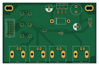
About the Lcr addon PCB
Lcr addon is an open source PCB design by BadenLab, published on GitHub under the MIT license. It is a 2-layer board measuring 85.1 × 55.1 mm, with 19 components from 19 distinct parts.
Other key parts include the 1727-3148-1, Blue channel, LM2596T-5.0/NOPB, RED+blank and Green+blank. By type, the board carries 8 ICs, 6 connectors, 2 capacitors, 1 diode, 1 inductor and 1 resistor.
It belongs with the test & measurement designs in this gallery.
From the project
An arbitrary-spectrum spatial visual stimulator for vision research
A board for integrating signals from a lightcrafter to a 2P microscope ("logic board"), part of the Open source visual stimulator project.
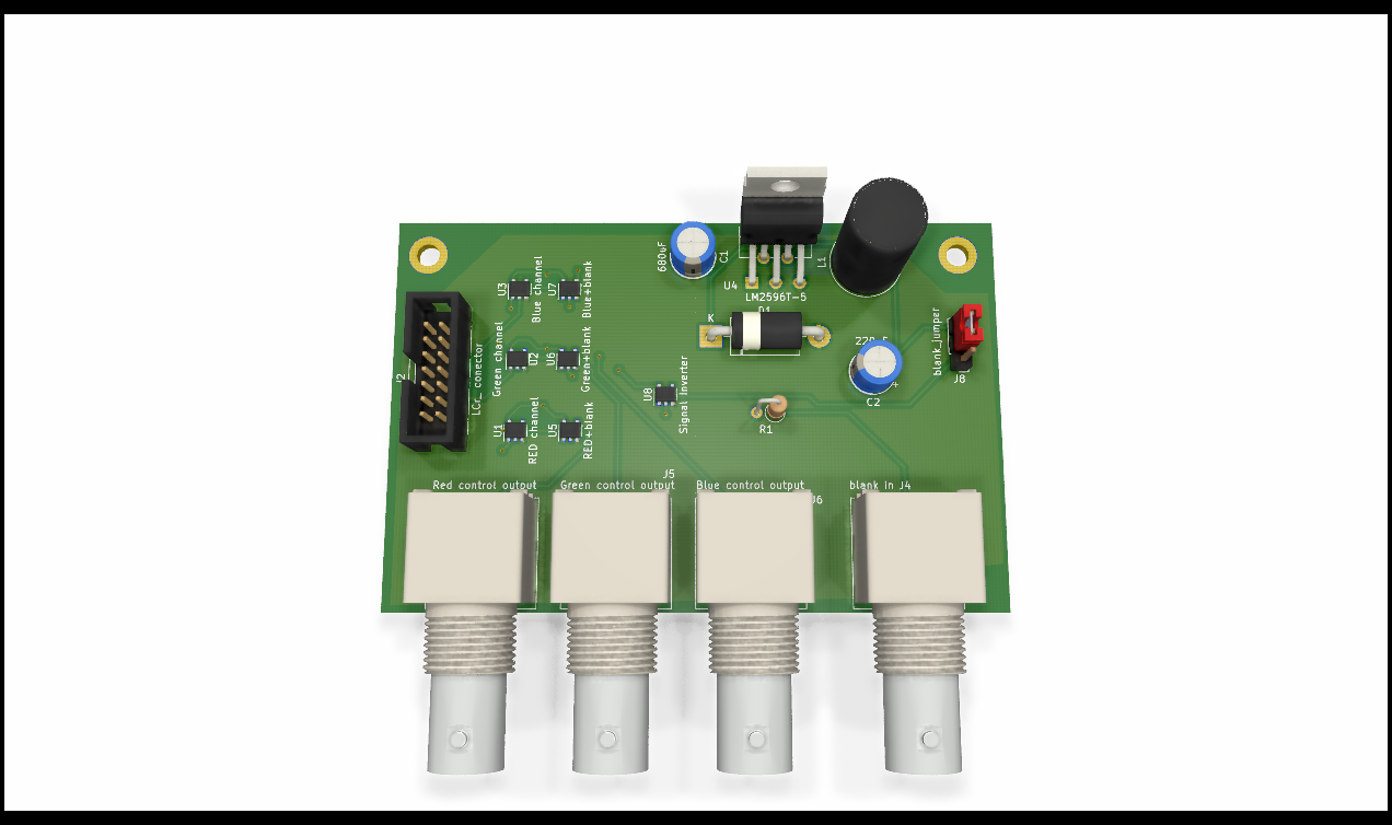
Main components on the Lcr addon
Lcr addon bill of materials (BOM)
19 components, 19 distinct parts — part numbers from the project's BOM.
| Qty | Part | Footprint | Refs |
|---|---|---|---|
| 1 | 1727-3148-1 RED channel NXP | TSOP-5_1.65x3.05mm_P0.95mm | U1 |
| 1 | 1727-3148-1 Green channel NXP | TSOP-5_1.65x3.05mm_P0.95mm | U2 |
| 1 | Blue channel | TSOP-5_1.65x3.05mm_P0.95mm | U3 |
| 1 | LM2596T-5.0/NOPB LM2596T-5 ITO-220 | TO-220-5_P3.4x3.7mm_StaggerOdd_Lead3.8mm_Vertical | U4 |
| 1 | RED+blank | TSOP-5_1.65x3.05mm_P0.95mm | U5 |
| 1 | Green+blank | TSOP-5_1.65x3.05mm_P0.95mm | U6 |
| 1 | Blue+blank | TSOP-5_1.65x3.05mm_P0.95mm | U7 |
| 1 | 74AHC1G14SE-7DI Signal Inverter Toshiba | TSOP-5_1.65x3.05mm_P0.95mm | U8 |
| 1 | 455-1764 LCr_ conector JST | JST_PUD_B14B-PUDSS_2x07_P2.00mm_Vertical | J2 |
| 1 | 1-1337542-0 blank in TE | BNC_Amphenol_B6252HB-NPP3G-50_Horizontal | J4 |
| 1 | 1-1337542-0 Green control output TE | BNC_Amphenol_B6252HB-NPP3G-50_Horizontal | J5 |
| 1 | 1-1337542-0 Blue control output TE | BNC_Amphenol_B6252HB-NPP3G-50_Horizontal | J6 |
| 1 | 1-1337542-0 Red control output TE | BNC_Amphenol_B6252HB-NPP3G-50_Horizontal | J7 |
| 1 | SSW-103-01-G-S blank_jumper SamTec | PinHeader_1x03_P2.54mm_Vertical | J8 |
| 1 | 1N5822-E3/73 D_Schottky Vishay | D_DO-201AD_P15.24mm_Horizontal | D1 |
| 1 | RLB0914-330KL 33uH Bourns | L_Radial_D10.0mm_P5.00mm_Neosid_SD12_style3 | L1 |
| 1 | 16ZL680MEFC10X16 680uF Rubycon | CP_Radial_D6.3mm_P2.50mm | C1 |
| 1 | EEU-FM1E221 220uF Panasonic | CP_Radial_D6.3mm_P2.50mm | C2 |
| 1 | 1.00KXBK 1k Multicomp | R_Axial_DIN0207_L6.3mm_D2.5mm_P2.54mm_Vertical | R1 |
Lcr addon design files
The KiCad project lives in the BadenLab/Open-Visual-Stimulator repository on GitHub; these links point at the commit this page was built from.
Lcr addon: common questions
How big is the Lcr addon PCB?
The Lcr addon measures 85.1 × 55.1 mm, has 2 copper layers and is 1.6 mm thick.
How many components are on the Lcr addon?
19 components, from 19 distinct parts, with part numbers taken from the project's own BOM. The full bill of materials is listed on this page.
Where can I download the Lcr addon design files?
From the BadenLab/Open-Visual-Stimulator repository on GitHub, which has the KiCad layout and the BOM; the links under Design files point to each one.
Can I use the Lcr addon design in my own project?
Yes, under the terms of its MIT license, which BadenLab chose for the repository.
More boards in Open-Visual-Stimulator
Similar boards
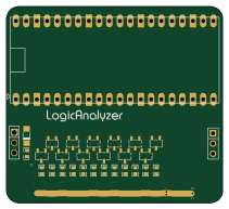
AnalyzerBoxPCB fork
gusmanb
52.7 × 47.9 mm54 parts4LGPL-3.05.0k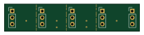
StackLink
52.3 × 10.5 mm5 parts2LGPL-3.05.0k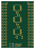
LevelShifter
28.3 × 39.8 mm21 parts2LGPL-3.05.0k
EleLab v2 PowerFeed
Chrismettal
68 × 50 mm11 parts2LGPL-3.0528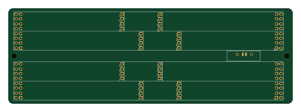
EleLab v2 Bus150
150 × 50 mm37 parts2LGPL-3.0528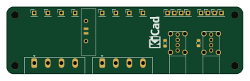
EleLab v2 Frontpanel a
88 × 25 mm23 parts2LGPL-3.0528