
Led driver

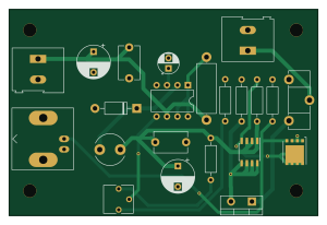
About the Led driver PCB
Led driver is an open source PCB design by BadenLab, published on GitHub under the MIT license. It is a 2-layer board measuring 75 × 50 mm, with 22 components from 19 distinct parts.
Other key parts include the MC34063AP. By type, the board carries 7 resistors, 5 capacitors, 3 connectors, 2 transistors, 1 IC and 1 diode.
It belongs with the test & measurement designs in this gallery.
From the project
An arbitrary-spectrum spatial visual stimulator for vision research
A board that contains a voltage regulator and a fast switching (tens of microsseconds) circuit for turning LEDs on and off
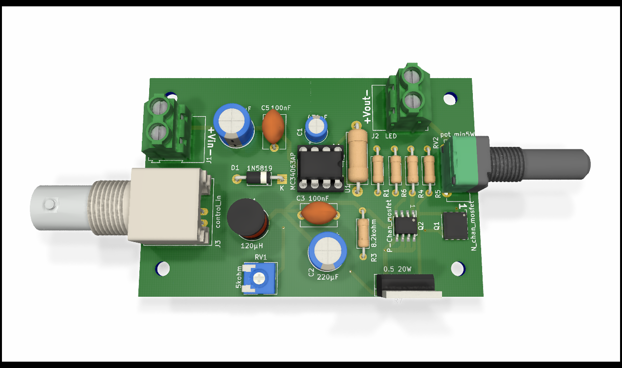
Main components on the Led driver
Led driver bill of materials (BOM)
22 components, 19 distinct parts — part numbers from the project's BOM.
| Qty | Part | Footprint | Refs |
|---|---|---|---|
| 1 | MC34063AP texas instruments | DIP-8_W7.62mm | U1 |
| 1 | SI4840BDY-T1-GE3 N_chan_mosfet Vishay | TDSON-8-1 | Q1 |
| 1 | FDS6575 P-Chan_mosfet Fairchild | SOIC-8_3.9x4.9mm_P1.27mm | Q2 |
| 1 | 494-8956 Vin RS Pro | TerminalBlock_Altech_AK300-2_P5.00mm | J1 |
| 1 | 494-8956 LED RS Pro | TerminalBlock_Altech_AK300-2_P5.00mm | J2 |
| 1 | 1-1337542-0 control_in TE | BNC_Amphenol_B6252HB-NPP3G-50_Horizontal | J3 |
| 1 | 3362P-1-502LF 5kohm Bourns | Potentiometer_Vishay_T73YP_Vertical | RV1 |
| 1 | 026TB32R250B1A1 pot_min5W CTS | Potentiometer_ACP_CA14-H5_Horizontal | RV2 |
| 1 | 1N5819G 1N5819 ON | D_DO-41_SOD81_P10.16mm_Horizontal | D1 |
| 1 | ELC11D121F 120µH Panasonic | L_Radial_D7.5mm_P5.00mm_Fastron_07P | L1 |
| 1 | 562R10TST47 470pF Vishay | CP_Radial_D5.0mm_P2.50mm | C1 |
| 2 | MAL214650221E3 220µF Vishay | CP_Radial_D8.0mm_P5.00mm | C2, C4 |
| 2 | MKS2D031001A00KI00 100nF Wima | C_Disc_D8.0mm_W5.0mm_P7.50mm | C3, C5 |
| 1 | LR1F1K5 1.5kohm TE Connectivity | R_Axial_DIN0207_L6.3mm_D2.5mm_P10.16mm_Horizontal | R1 |
| 1 | RWM0410R220JR15E1 0.22ohm Vishay | R_Axial_DIN0414_L11.9mm_D4.5mm_P15.24mm_Horizontal | R2 |
| 1 | LR1F8K2 8.2kohm TE Connectivity | R_Axial_DIN0207_L6.3mm_D2.5mm_P10.16mm_Horizontal | R3 |
| 2 | MFR-25FBF52-220R 220 Yageo | R_Axial_DIN0207_L6.3mm_D2.5mm_P10.16mm_Horizontal | R4, R5 |
| 1 | 1.00KXBK 1k Multicomp | R_Axial_DIN0207_L6.3mm_D2.5mm_P10.16mm_Horizontal | R6 |
| 1 | PWR220T-20-R500F 0.5 20W Bourns | TO-220-2_Vertical | R7 |
Led driver design files
The KiCad project lives in the BadenLab/Open-Visual-Stimulator repository on GitHub; these links point at the commit this page was built from.
Led driver: common questions
How big is the Led driver PCB?
The Led driver measures 75 × 50 mm, has 2 copper layers and is 1.6 mm thick.
How many components are on the Led driver?
22 components, from 19 distinct parts, with part numbers taken from the project's own BOM. The full bill of materials is listed on this page.
Where can I download the Led driver design files?
From the BadenLab/Open-Visual-Stimulator repository on GitHub, which has the KiCad layout and the BOM; the links under Design files point to each one.
Can I use the Led driver design in my own project?
Yes, under the terms of its MIT license, which BadenLab chose for the repository.
More boards in Open-Visual-Stimulator
Similar boards
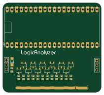
AnalyzerBoxPCB fork
gusmanb
52.7 × 47.9 mm54 parts4LGPL-3.05.0k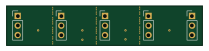
StackLink
52.3 × 10.5 mm5 parts2LGPL-3.05.0k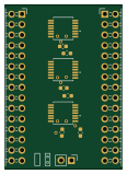
LevelShifter
28.3 × 39.8 mm21 parts2LGPL-3.05.0k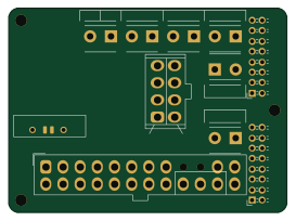
EleLab v2 PowerFeed
Chrismettal
68 × 50 mm11 parts2LGPL-3.0528
EleLab v2 Bus150
150 × 50 mm37 parts2LGPL-3.0528
EleLab v2 Frontpanel a
88 × 25 mm23 parts2LGPL-3.0528