
Gd VGC proto

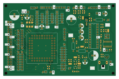
About the Gd VGC proto PCB
Gd VGC proto is an open source PCB design by baldengineer, published on GitHub under the MIT license. It is a 4-layer board measuring 114.3 × 73.7 mm, with 117 components from 68 distinct parts.
Other key parts include the MIC5504-3.3YM5 and 28.636360 MHz. By type, the board carries 39 capacitors, 28 connectors, 22 resistors, 12 test points, 3 transistors and 3 inductors.
From the project
Using the Mega II from a IIgs to make a Apple IIe compatible computer: The Mega IIe!
First board to be finished and the one with the least use for the final handheld. The VGC converts the RGB bitstream from the MEGA-II into an analog signal and then into NTSC.
The VGC also generates the 14 MHz clock from a 28 MHz oscilliator. (It is not clear yet which clocks the MEGA-II generates and which the VGC does.)
Runs off of +5V, -5V, and +12V. The 12V and -5V are used by the NTSC generation circuit.
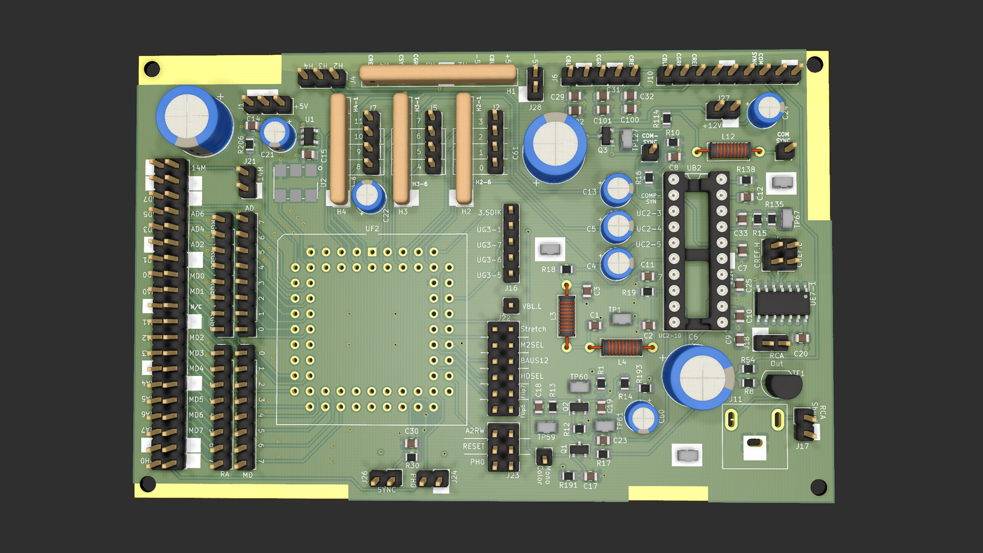
Main components on the Gd VGC proto
Gd VGC proto bill of materials (BOM)
117 components, 68 distinct parts.
| Qty | Part | Footprint | Refs |
|---|---|---|---|
| 1 | MIC5504-3.3YM5 | SOT-23-5 | U1 |
| 1 | 28.636360 MHz | Oscillator_SMD_IDT_JU6-6_7.0x5.0mm_P2.54mm | U2 |
| 3 | BC817 | SOT-23 | Q1, Q2, Q3 |
| 1 | +5V_IN | PinHeader_1x03_P2.54mm_Vertical | J1 |
| 1 | Video Binary B | PinHeader_1x04_P2.54mm_Vertical | J2 |
| 1 | Aux Data Bus | PinHeader_1x08_P2.54mm_Vertical | J3 |
| 1 | DAC RGB | PinHeader_1x03_P2.54mm_Vertical | J4 |
| 1 | Video Binary G | PinHeader_1x04_P2.54mm_Vertical | J5 |
| 1 | COMP_RGB | PinHeader_1x05_P2.54mm_Vertical | J6 |
| 1 | Video Binary R | PinHeader_1x04_P2.54mm_Vertical | J7 |
| 1 | RAM Addr Bus | PinHeader_1x08_P2.54mm_Vertical | J8 |
| 1 | Composite Sync | PinHeader_1x01_P2.54mm_Vertical | J9 |
| 1 | VID_OUT | PinHeader_1x09_P2.54mm_Vertical | J10 |
| 1 | PJRAN1X1U02AUX RCA MONO OUT | Jack_RCA_Switchcraft_PJRAN1X1UxxX | J11 |
| 1 | Main Data Bus | PinHeader_1x08_P2.54mm_Vertical | J12 |
| 1 | COMSYNC | PinHeader_1x01_P2.54mm_Vertical | J13 |
| 1 | Mono-Color | PinHeader_1x01_P2.54mm_Vertical | J14 |
| 1 | VBL | PinHeader_1x01_P2.54mm_Vertical | J15 |
| 1 | RTC | PinHeader_1x05_P2.54mm_Vertical | J16 |
| 1 | RCA Shunt Select | PinHeader_1x02_P2.54mm_Vertical | J17 |
Show 48 more
| Qty | Part | Footprint | Refs |
|---|---|---|---|
| 1 | RCA | PinHeader_1x02_P2.54mm_Vertical | J18 |
| 1 | CREF | PinHeader_2x02_P2.54mm_Vertical | J19 |
| 1 | RGB In | PinHeader_1x08_P2.54mm_Vertical | J20 |
| 1 | CLK_14M | PinHeader_1x02_P2.54mm_Vertical | J21 |
| 1 | Memory Control | PinHeader_2x06_P2.54mm_Vertical | J22 |
| 1 | VGC Extra | PinHeader_2x03_P2.54mm_Vertical | J23 |
| 1 | CLK_PH0 | PinHeader_1x02_P2.54mm_Vertical | J24 |
| 1 | Bald-Ext-1 | PinHeader_2x20_P2.54mm_Vertical | J25 |
| 1 | SYNC | PinHeader_1x02_P2.54mm_Vertical | J26 |
| 1 | 12V_IN | PinHeader_1x02_P2.54mm_Vertical | J27 |
| 1 | -5V_In | PinHeader_1x02_P2.54mm_Vertical | J28 |
| 1 | Video_Sync | R_Array_SIP10 | H1 |
| 3 | VideoThingy | R_Array_SIP7 | H2, H3, H4 |
| 1 | CapacitiveTransformer | TO-92 | TF1 |
| 12 | TestPoint | Harwin-S1751-46-Test-Point | TP1, TP2, TP3, TP4, TP5, TP59, TP60, TP61 +4 |
| 1 | MC1377 | DIP-20_W7.62mm_Socket | UB2 |
| 1 | 74LS02 | SOIC-14_3.9x8.7mm_P1.27mm | UE7-1 |
| 1 | VGC | PLCC-68_THT-Socket | UF2 |
| 2 | 10u | L_Axial_L6.6mm_D2.7mm_P10.16mm_Horizontal_Vishay_IM-2 | L3, L4 |
| 1 | 1.5u | L_Axial_L6.6mm_D2.7mm_P10.16mm_Horizontal_Vishay_IM-2 | L12 |
| 3 | 56p | C_0805_2012Metric | C1, C23, C30 |
| 2 | 18p | C_0805_2012Metric | C2, C3 |
| 3 | 22uF | CP_Radial_D5.0mm_P2.00mm | C4, C5, C13 |
| 3 | 22uF | C_0805_2012Metric | C4alt1, C5alt1, C6alt1 |
| 1 | 1000u | CP_Radial_D10.0mm_P2.50mm | C6 |
| 4 | 0.1u | C_0805_2012Metric | C7, C9, C10, C17 |
| 1 | 1n | C_0805_2012Metric | C8 |
| 2 | 0.01u | C_0805_2012Metric | C11, C12 |
| 2 | 1uF | C_0805_2012Metric | C14, C15 |
| 2 | 470u | CP_Radial_D10.0mm_P2.50mm | C16, C61 |
| 1 | 27p | C_0805_2012Metric | C18 |
| 1 | .001u | C_0805_2012Metric | C19 |
| 1 | 100n | C_0805_2012Metric | C20 |
| 3 | 10u | CP_Radial_D5.0mm_P2.50mm | C21, C22, C24 |
| 2 | 1u | C_0805_2012Metric | C25, C59 |
| 3 | 33p | C_0805_2012Metric | C29, C31, C32 |
| 1 | 220p | C_0805_2012Metric | C33 |
| 1 | 22u | CP_Radial_D5.0mm_P2.50mm | C60 |
| 3 | 120p | C_0805_2012Metric | C100, C101, C102 |
| 1 | 0 | R_0805_2012Metric | R1 |
| 3 | 75 | R_0805_2012Metric | R8, R54, R206 |
| 3 | 220 | R_0805_2012Metric | R9, R12, R114 |
| 2 | 1.5K | R_0805_2012Metric | R10, R15 |
| 5 | 1k | R_0805_2012Metric | R11, R13, R14, R17, R30 |
| 1 | 51k | R_0805_2012Metric | R16 |
| 3 | 470 | R_0805_2012Metric | R18, R19, R135 |
| 2 | 100 | R_0805_2012Metric | R138, R193 |
| 2 | 4.7k | R_0805_2012Metric | R191, R196 |
Gd VGC proto design files
The KiCad project lives in the baldengineer/Mega-IIe repository on GitHub; these links point at the commit this page was built from.
Gd VGC proto: common questions
How big is the Gd VGC proto PCB?
The Gd VGC proto measures 114.3 × 73.7 mm, has 4 copper layers and is 1.6 mm thick.
How many components are on the Gd VGC proto?
117 components, from 68 distinct parts. The full bill of materials is listed on this page.
Where can I download the Gd VGC proto design files?
From the baldengineer/Mega-IIe repository on GitHub, which has the KiCad layout and the schematic; the links under Design files point to each one.
Can I use the Gd VGC proto design in my own project?
Yes, under the terms of its MIT license, which baldengineer chose for the repository.
More boards in Mega-IIe
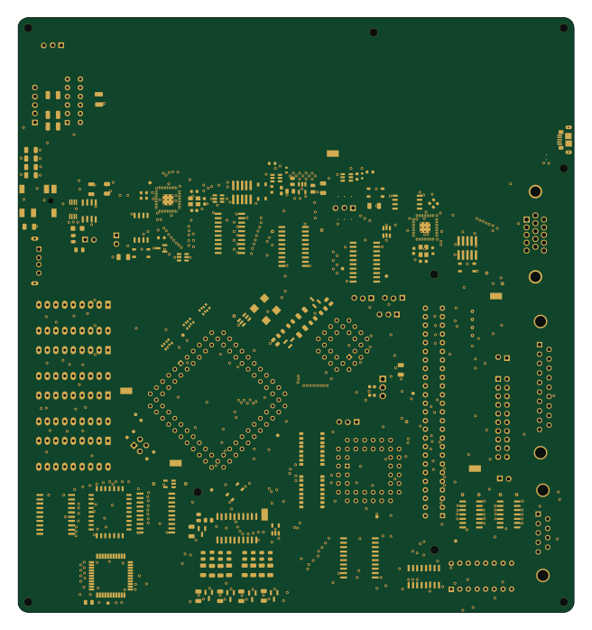 RP2040/RP2350
Mega IIe
163 × 174.4 mm307 parts4LMIT33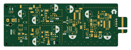
GD Power Supply Proto
135.2 × 46.8 mm117 parts4LMIT33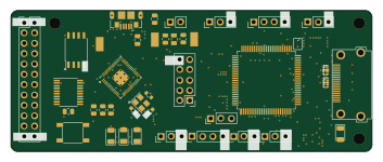 RP2040/RP2350
Servid rp2040-hdmi proto rev1
88.1 × 34.5 mm99 parts4LMIT33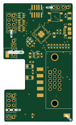 RP2040/RP2350
VGA Proto
37.1 × 63.8 mm62 parts2LMIT33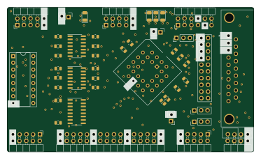
Gd IWM proto
93.2 × 54.7 mm60 parts2LMIT33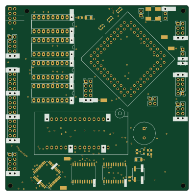
Gd MEGA-65c02 proto
98.8 × 100 mm56 parts4LMIT33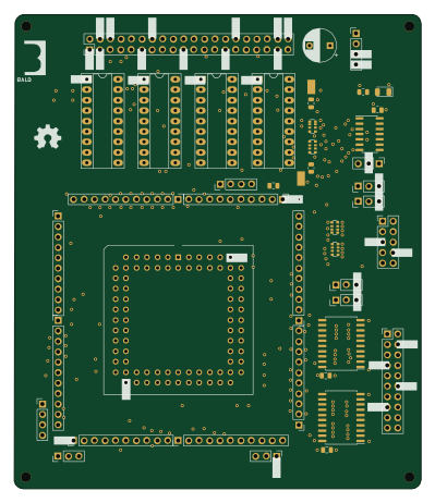
Gd MegaII proto
98.8 × 115.3 mm56 parts4LMIT33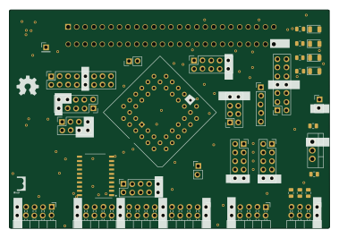
IO Prototype (aka Slot)
94.8 × 64.6 mm37 parts2LMIT33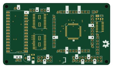
Gd 6502 proto
90.4 × 52.2 mm34 parts4LMIT33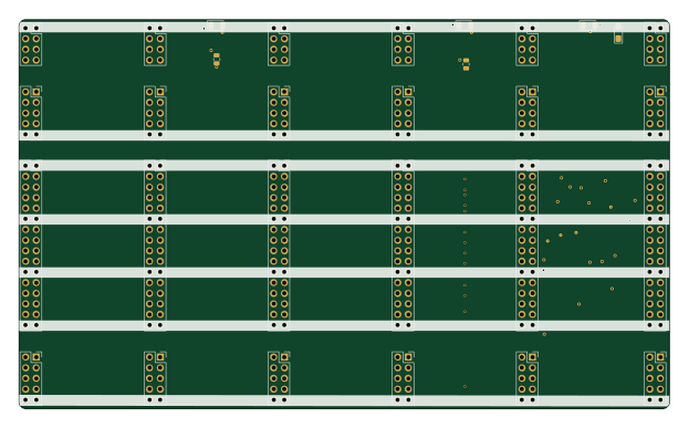
Gd blackplane proto
155.5 × 93 mm33 parts2LMIT33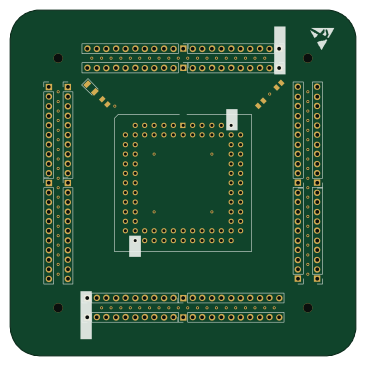
MegaII Breakout
91.4 × 91.4 mm21 parts2LMIT33