
Can converter

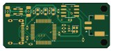
About the Can converter PCB
Can converter is an open source STM32 PCB design by bluesatunsw, published on GitHub under the Apache-2.0 license. It is a 2-layer board measuring 40.6 × 17.2 mm, with 25 components from 18 distinct parts.
Its main chip is the STM32G0B1CBT, from the STM32 family. Other key parts include the TCAN1462V. By type, the board carries 8 capacitors, 8 resistors, 3 diodes, 2 ICs, 2 crystals and 1 connector.
From the project
This repo includes all software necessary to operate the Test Rover Platform that is being designed and developed in the 502 project.
USB CANFD Device, based on the upstream CandleLightFD project (STM32G4 variant)
A small USB-C device that allows for the reading of can signals from the rover.
The device uses 5V power from the USB-C port to power, with a buck converter for the 3.3V power on the board. The CAN signals are processed by the TCAN1462V transceiver. The transceiver is connected to the STM32 with data signals RXD, TXD and a standby input. The STM32 also interfaces with two LEDs to display the functionality of the device and actions it's currently performing. CAN signals are processed by the STM32 and sent to the…
Main components on the Can converter
Can converter bill of materials (BOM)
25 components, 18 distinct parts.
| Qty | Part | Footprint | Refs |
|---|---|---|---|
| 1 | STM32G0B1CBT ST | LQFP-48-0.5 | U1 |
| 1 | TCAN1462V | SOIC-8_3.9x4.9mm_P1.27mm | U2 |
| 1 | 629722000214 629722000214_pasteInHole Würth Elektronik | USB_C_Receptacle_USB2.0_14P | X1 |
| 1 | 830108313809 Würth Elektronik | Crystal_SMD_2016-4Pin_2.0x1.6mm | Y1 |
| 1 | SM02B-PASS | SM02B-PASS | J1 |
| 1 | RT9013-33GB | SOT-23-5 | PS1 |
| 1 | KPT-1608SGC XL-1608UYC-06 Kingbright | LED_0603_1608Metric | D1 |
| 1 | KPT-1608SGC XL-1608UGC-04 Kingbright | LED_0603_1608Metric | D2 |
| 1 | KPT-1608EC XL-1608SURC-06 Kingbright | LED_0603_1608Metric | D3 |
| 2 | any 10p any | C_0402_1005Metric | C1, C2 |
| 1 | MC0603B104K500CT 10n Multicomp | C_0402_1005Metric | C3 |
| 1 | MC0603B104K500CT 220n Multicomp | C_0402_1005Metric | C4 |
| 2 | any 10u any | C_1206_3216Metric | C6, C7 |
| 2 | any 220n any | C_0402_1005Metric | C8, C9 |
| 2 | any 4K7 any | R_0402_1005Metric | R1, R2 |
| 3 | any 1K any | R_0402_1005Metric | R3, R4, R5 |
| 2 | 100k | R_0402_1005Metric | R7, R8 |
| 1 | 470R | R_0402_1005Metric | R9 |
Can converter design files
The KiCad project lives in the bluesatunsw/owr repository on GitHub; these links point at the commit this page was built from.
Can converter: common questions
What microcontroller does the Can converter use?
The Can converter is built around the STM32G0B1CBT, from the STM32 family.
How big is the Can converter PCB?
The Can converter measures 40.6 × 17.2 mm, has 2 copper layers and is 1.6 mm thick.
How many components are on the Can converter?
25 components, from 18 distinct parts. The full bill of materials is listed on this page.
Where can I download the Can converter design files?
From the bluesatunsw/owr repository on GitHub, which has the KiCad layout and the schematic; the links under Design files point to each one.
Can I use the Can converter design in my own project?
Yes, under the terms of its Apache-2.0 license, which bluesatunsw chose for the repository.
Can I test firmware for the Can converter without the hardware?
Yes. HardLabs builds a simulation of the board from its netlist and BOM, so you can run and debug STM32 firmware against it before you order a PCB.
More boards in owr
 STM32
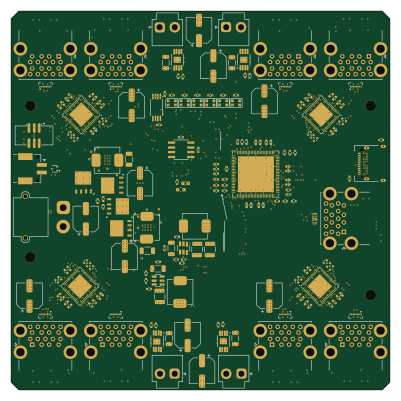
STM32Usb power board
100 × 100 mm404 parts6LApache-2.05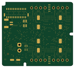 STM32
STM32Stepper driver
62 × 55.5 mm204 parts6LApache-2.05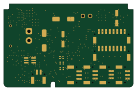 STM32
STM32Computing power hub
70 × 45 mm182 parts6LApache-2.05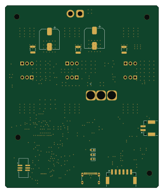 STM32
STM32Vesc
80 × 95 mm153 parts6LApache-2.05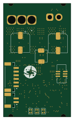 STM32
STM32Vesc2
37 × 62 mm123 parts6LApache-2.05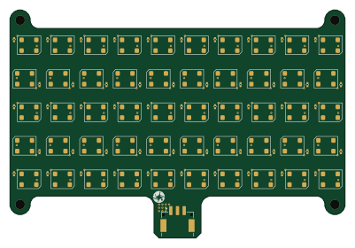
LED Beacon
100 × 68 mm101 parts2LApache-2.05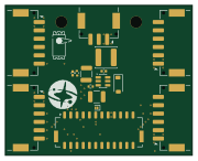
Connector board
45 × 36 mm16 parts2LApache-2.05
Bluesat encoder board
30 × 23 mm3 parts2LApache-2.05
Similar boards
 STM32
STM32LumenPnP Motherboard
opulo-inc
149 × 95 mm296 parts4LCC-BY-SA-4.03.7k STM32
STM32AxxSolder
AxxAxx
39 × 82.5 mm122 parts2LGPL-3.01.7k STM32
STM32AIOC
skuep
21 × 31.5 mm47 parts2LMIT1.4k STM32
STM32Ferris
pierrechevalier83
208.8 × 86.8 mm102 parts2LSHL-2.11.3k STM32
STM32176 pin board
rusefi
61.8 × 73.2 mm76 parts2LGPL-3.01.2k STM32
STM32Brain board STM32F407
61.8 × 73.2 mm69 parts2LGPL-3.01.2k