
Connector board

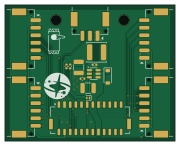
About the Connector board
Connector board is an open source PCB design by bluesatunsw, published on GitHub under the Apache-2.0 license. It is a 2-layer board measuring 45 × 36 mm, with 16 components from 13 distinct parts.
Other key parts include the MP2459GJ-Z-MS. By type, the board carries 6 connectors, 4 capacitors, 2 diodes, 2 resistors, 1 IC and 1 inductor.
From the project
This repo includes all software necessary to operate the Test Rover Platform that is being designed and developed in the 502 project.
Main components on the Connector board
Connector board bill of materials (BOM)
16 components, 13 distinct parts.
| Qty | Part | Footprint | Refs |
|---|---|---|---|
| 1 | MP2459GJ-Z-MS | TSOT-23-6 | U2 |
| 1 | Conn_02x12_Odd_Even | BM24B-ZPDSS | J1 |
| 4 | Conn_01x06 | SM06B-PASS | J2, J3, J4, J5 |
| 1 | Conn_01x03 | SM03B-PASS | J6 |
| 1 | D_Schottky_Small | D_SOD-882 | D1 |
| 1 | D_Schottky_Small | D_SOD-123 | D2 |
| 1 | 15u | L_Changjiang_FNR5040S | L221 |
| 1 | 22u | C_1210_3225Metric | C1 |
| 1 | 4u7 | C_1210_3225Metric | C7 |
| 1 | 100n | C_0402_1005Metric | C8 |
| 1 | 33p | C_0402_1005Metric | C12 |
| 1 | 68k | R_0402_1005Metric | R6 |
| 1 | 10k | R_0402_1005Metric | R7 |
Connector board design files
The KiCad project lives in the bluesatunsw/owr repository on GitHub; these links point at the commit this page was built from.
Connector board: common questions
How big is the Connector board?
The Connector board measures 45 × 36 mm, has 2 copper layers and is 1.6 mm thick.
How many components are on the Connector board?
16 components, from 13 distinct parts. The full bill of materials is listed on this page.
Where can I download the Connector board design files?
From the bluesatunsw/owr repository on GitHub, which has the KiCad layout and the schematic; the links under Design files point to each one.
Can I use the Connector board design in my own project?
Yes, under the terms of its Apache-2.0 license, which bluesatunsw chose for the repository.
More boards in owr
 STM32
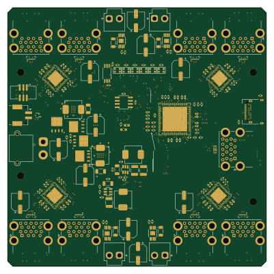
STM32Usb power board
100 × 100 mm404 parts6LApache-2.05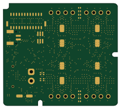 STM32
STM32Stepper driver
62 × 55.5 mm204 parts6LApache-2.05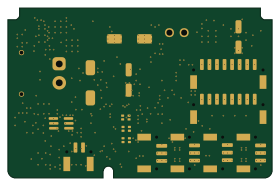 STM32
STM32Computing power hub
70 × 45 mm182 parts6LApache-2.05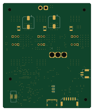 STM32
STM32Vesc
80 × 95 mm153 parts6LApache-2.05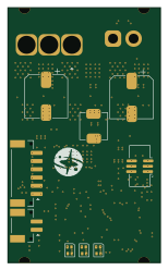 STM32
STM32Vesc2
37 × 62 mm123 parts6LApache-2.05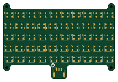
LED Beacon
100 × 68 mm101 parts2LApache-2.05 STM32
STM32Can converter
40.6 × 17.2 mm25 parts2LApache-2.05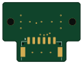
Bluesat encoder board
30 × 23 mm3 parts2LApache-2.05