
Griffin

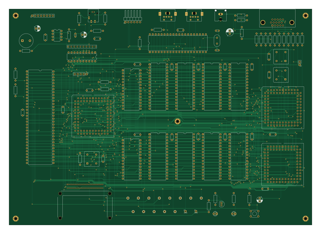
About the Griffin PCB
Griffin is an open source PCB design by bradgrantham, published on GitHub under the Apache-2.0 license. It is a 4-layer board measuring 260.6 × 185.6 mm, with 110 components from 69 distinct parts.
Other key parts include the MC68000P, ROM LO, ROM HI, RAM 1 LO and RAM 1 HI. By type, the board carries 31 resistors, 28 capacitors, 17 ICs, 15 test points, 10 connectors and 4 crystals.
From the project
An M68000 homebrew SBC. See the design notes.
Main components on the Griffin
Griffin bill of materials (BOM)
110 components, 69 distinct parts.
| Qty | Part | Footprint | Refs |
|---|---|---|---|
| 1 | MC68000P | DIP-64_W22.86mm | U1 |
| 1 | ROM LO | DIP-28_W15.24mm | U2 |
| 1 | ROM HI | DIP-28_W15.24mm | U3 |
| 1 | RAM 1 LO | DIP-32_W15.24mm | U4 |
| 1 | RAM 1 HI | DIP-32_W15.24mm | U5 |
| 1 | RAM 2 LO | DIP-32_W15.24mm | U6 |
| 1 | RAM 2 HI | DIP-32_W15.24mm | U7 |
| 1 | RAM 3 LO | DIP-32_W15.24mm | U8 |
| 1 | RAM 3 HI | DIP-32_W15.24mm | U9 |
| 1 | RAM 4 LO | DIP-32_W15.24mm | U10 |
| 1 | RAM 4 HI | DIP-32_W15.24mm | U11 |
| 1 | GLUE | PLCC-84_THT-Socket | U12 |
| 1 | ENGINE | PLCC-84_THT-Socket | U13 |
| 1 | LM358 | DIP-8_W7.62mm | U15 |
| 1 | AT89x51xxP | DIP-40_W15.24mm | U16 |
| 1 | VIDEO | PLCC-84_THT-Socket | U17 |
| 1 | 74HC373 | DIP-20_W7.62mm | U23 |
| 1 | PN2222A | TO-92_Inline | Q2 |
| 1 | 14.318MHz | Oscillator_DIP-8 | Y1 |
| 1 | 11.0592MHz | Resonator-2Pin_W10.0mm_H5.0mm | Y2 |
Show 49 more
| Qty | Part | Footprint | Refs |
|---|---|---|---|
| 1 | 25.175MHz | Oscillator_DIP-8 | Y3 |
| 1 | 12MHz | Oscillator_DIP-8 | Y4 |
| 1 | Conn_01x05_Pin | PinHeader_1x05_P2.54mm_Vertical | J1 |
| 1 | KEYBOARD | Mini_din6 | J2 |
| 1 | AdaFruit 4090 USB-C BOB | PinHeader_1x08_P2.54mm_Vertical | J3 |
| 1 | MOUSE | Mini_din6 | J4 |
| 1 | VIDEO_JTAG_BYPASS | PinHeader_1x02_P2.54mm_Vertical | J5 |
| 1 | COMPOSITE | CUI_RCJ-044 | J6 |
| 1 | STEREO_OUT | SAMESKY_SJ3-35063B | J7 |
| 1 | CF Card | SAMTEC_CFT-125-01-L-D-RA-01-SL | J8 |
| 1 | FTDI serial | PinHeader_1x06_P2.54mm_Horizontal | J9 |
| 1 | VGA | AMPHENOL_ICD15S13E4GX00LF | J10 |
| 1 | Speaker | MagneticBuzzer_StarMicronics_QMX | LS1 |
| 1 | RESET | SW_TH_Tactile_Omron_B3F-106x | SW1 |
| 1 | Debug In | PinHeader_1x01_P2.54mm_Vertical | TP1 |
| 1 | Debug Out | PinHeader_1x01_P2.54mm_Vertical | TP2 |
| 1 | CLK | TestPoint_THTPad_D2.0mm_Drill1.0mm | TP3 |
| 1 | ~{RESET} | TestPoint_THTPad_D2.0mm_Drill1.0mm | TP4 |
| 1 | ~{HALT} | TestPoint_THTPad_D2.0mm_Drill1.0mm | TP5 |
| 1 | ~{AS} | TestPoint_THTPad_D2.0mm_Drill1.0mm | TP6 |
| 1 | ~{DTACK} | TestPoint_THTPad_D2.0mm_Drill1.0mm | TP7 |
| 1 | R/~{W} | TestPoint_THTPad_D2.0mm_Drill1.0mm | TP8 |
| 1 | ~{LDS} | TestPoint_THTPad_D2.0mm_Drill1.0mm | TP9 |
| 1 | ~{UDS} | TestPoint_THTPad_D2.0mm_Drill1.0mm | TP10 |
| 1 | FC0 | TestPoint_THTPad_D2.0mm_Drill1.0mm | TP11 |
| 1 | FC1 | TestPoint_THTPad_D2.0mm_Drill1.0mm | TP12 |
| 1 | FC2 | TestPoint_THTPad_D2.0mm_Drill1.0mm | TP13 |
| 1 | ~{ROM_SELECT} | TestPoint_THTPad_D2.0mm_Drill1.0mm | TP14 |
| 1 | ~{RAM_SELECT_1} | TestPoint_THTPad_D2.0mm_Drill1.0mm | TP15 |
| 1 | GREEN | LED_D3.0mm | D1 |
| 1 | RED | LED_D3.0mm | D2 |
| 2 | 10uF | CP_Radial_D5.0mm_P2.50mm | C1, C3 |
| 21 | 100nF | C_Disc_D5.0mm_W2.5mm_P5.00mm | C2, C4, C5, C6, C7, C8, C9, C10 +13 |
| 2 | 15pF | C_Disc_D3.0mm_W1.6mm_P2.50mm | C21, C22 |
| 1 | 10nF | C_Disc_D3.0mm_W1.6mm_P2.50mm | C25 |
| 1 | 100µF | CP_Radial_D5.0mm_P2.50mm | C26 |
| 1 | 220µF | CP_Radial_D6.3mm_P2.50mm | C35 |
| 4 | 100 | R_Axial_DIN0207_L6.3mm_D2.5mm_P10.16mm_Horizontal | R1, R5, R57, R58 |
| 6 | 10k | R_Axial_DIN0207_L6.3mm_D2.5mm_P10.16mm_Horizontal | R2, R6, R7, R9, R19, R56 |
| 3 | 100K | R_Axial_DIN0207_L6.3mm_D2.5mm_P10.16mm_Horizontal | R3, R4, R33 |
| 3 | 560 | R_Axial_DIN0207_L6.3mm_D2.5mm_P10.16mm_Horizontal | R12, R20, R26 |
| 3 | 1K | R_Axial_DIN0207_L6.3mm_D2.5mm_P10.16mm_Horizontal | R14, R52, R53 |
| 1 | 430 | R_Axial_DIN0207_L6.3mm_D2.5mm_P10.16mm_Horizontal | R15 |
| 1 | 33 | R_Axial_DIN0207_L6.3mm_D2.5mm_P10.16mm_Horizontal | R16 |
| 3 | 270 | R_Axial_DIN0207_L6.3mm_D2.5mm_P10.16mm_Horizontal | R21, R25, R31 |
| 2 | 1100 | R_Axial_DIN0207_L6.3mm_D2.5mm_P10.16mm_Horizontal | R22, R23 |
| 3 | 150 | R_Axial_DIN0207_L6.3mm_D2.5mm_P10.16mm_Horizontal | R40, R41, R42 |
| 1 | 47 | R_Axial_DIN0207_L6.3mm_D2.5mm_P10.16mm_Horizontal | R59 |
| 1 | 4610X-R2R-103LF | BO_4610X | R60 |
Griffin design files
The KiCad project lives in the bradgrantham/griffin repository on GitHub; these links point at the commit this page was built from.
- Layoutboard/board.kicad_pcb
- Schematicboard/board.kicad_sch
Griffin: common questions
How big is the Griffin PCB?
The Griffin measures 260.6 × 185.6 mm, has 4 copper layers and is 1.6 mm thick.
How many components are on the Griffin?
110 components, from 69 distinct parts. The full bill of materials is listed on this page.
Where can I download the Griffin design files?
From the bradgrantham/griffin repository on GitHub, which has the KiCad layout and the schematic; the links under Design files point to each one.
Can I use the Griffin design in my own project?
Yes, under the terms of its Apache-2.0 license, which bradgrantham chose for the repository.