
Analog-Input-Card

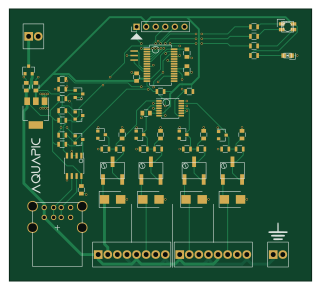
About the Analog-Input-Card PCB
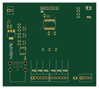
Analog-Input-Card is an open source PIC PCB design by brandtks, published on GitHub. It is a 2-layer board measuring 80 × 72 mm, with 59 components from 22 distinct parts.
Its main chip is the PIC32MM0064GPM028, from the PIC family. Other key parts include the ST485EC, MCP3428 and AP2114H. By type, the board carries 21 resistors, 11 capacitors, 10 diodes, 4 ICs, 4 transistors and 3 connectors.
From the project
AquaPic modules, board design and firmware
README ====== Board design and firmware for all modules used with the AquaPic Aquarium Controller. Each board should have corresponding firmware that works with that board version. All modules communicate with and are controlled by the master controller/head unit.
All PCB designs and layouts including gerber files are located under the Boards directory. All PCB design is done using KiCAD. Firmware is located in the Firmware directory. All the card's firmware should build without the need of the MPLAB X IDE, just the XC compilers. The Documentation directory contains some useful information…
Main components on the Analog-Input-Card
Analog-Input-Card bill of materials (BOM)
59 components, 22 distinct parts.
| Qty | Part | Footprint | Refs |
|---|---|---|---|
| 1 | PIC32MM0064GPM028 | SSOP-28_5.3x10.2mm_Pitch0.65mm | IC1 |
| 1 | ST485EC | SOIC-8_3.9x4.9mm_Pitch1.27mm | U1 |
| 1 | MCP3428 | TSSOP-14_4.4x5mm_Pitch0.65mm | U2 |
| 1 | AP2114H | SOT-223 | U3 |
| 1 | AO3407A | SOT-23 | Q1 |
| 3 | NX7002AK | SOT-23 | Q2, Q3, Q4 |
| 1 | 8MHz | Resonator_3.2x1.3 | X1 |
| 1 | usb1.1 | USB-1.1_Stacked | P1 |
| 1 | Inputs | Screw_Header_1x16 | P2 |
| 1 | Earth | Screw_Header_1x2 | P3 |
| 1 | 2x1 2.54 | Screw_Header_1x2 | 5Vdc |
| 4 | 10K | POTENTIAMETER_SMD | RV1, RV2, RV3, RV4 |
| 1 | SMTL4-RGY | PLCC-4 | D1 |
| 1 | APT2012 | LED-0805 | D2 |
| 4 | BZX84C3V3 | D_SOT-23_ANK | D3, D5, D7, D9 |
| 4 | SMBJ30D | D_SMB | D4, D6, D8, D10 |
| 9 | 100nF | C_0805 | C1, C2, C3, C4, C5, C6, C7, C8 +1 |
| 2 | 4u7 | C_0805 | C9, C10 |
| 4 | 150R | R_0805 | R1, R2, R3, R4 |
| 10 | 4K99 | R_0805 | R5, R6, R7, R9, R11, R13, R15, R16 +2 |
Show 2 more
| Qty | Part | Footprint | Refs |
|---|---|---|---|
| 6 | 10K | R_0805 | R8, R10, R12, R14, R20, R21 |
| 1 | 1K | R_0805 | R19 |
Analog-Input-Card design files
The KiCad project lives in the brandtks/AquaPicModules repository on GitHub; these links point at the commit this page was built from.
Analog-Input-Card: common questions
What microcontroller does the Analog-Input-Card use?
The Analog-Input-Card is built around the PIC32MM0064GPM028, from the PIC family.
How big is the Analog-Input-Card PCB?
The Analog-Input-Card measures 80 × 72 mm, has 2 copper layers and is 1.6 mm thick.
How many components are on the Analog-Input-Card?
59 components, from 22 distinct parts. The full bill of materials is listed on this page.
Where can I download the Analog-Input-Card design files?
From the brandtks/AquaPicModules repository on GitHub, which has the KiCad layout; the links under Design files point to each one.
Can I use the Analog-Input-Card design in my own project?
The repository has no license, so all rights stay with brandtks. Use it as a reference, and ask the author before reusing the design.
Can I test firmware for the Analog-Input-Card without the hardware?
Yes. HardLabs builds a simulation of the board from its netlist and BOM, so you can run and debug PIC firmware against it before you order a PCB.
More boards in AquaPicModules
Similar boards
 PIC
PICPslab hardware
fossasia
99 × 53.3 mm187 parts4LApache-2.01.7k PIC
PICMicro 8088
skiselev
152.4 × 101.6 mm71 partsGPL-3.0414 PIC
PICGB-CARTPP-DIY
Gekkio
100 × 100 mm22 parts2LCC-BY-4.0376 PIC
PICGB-MBCTEST
51.4 × 61 mm32 parts2LCC-BY-4.0376 PIC
PICGB-BENCH-G1
100 × 100 mm98 parts4LCC-BY-4.0376 PIC
PICGB-LIVE32
51.4 × 61 mm46 parts4LCC-BY-4.0376