
Data-Logger-STM32

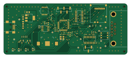
About the Data-Logger-STM32 PCB
Data-Logger-STM32 is an open source STM32 PCB design by can-caglar, published on GitHub. It is a 2-layer board measuring 104 × 43.3 mm, with 76 components from 37 distinct parts.
Its main chip is the STM32F303K8T6, from the STM32 family. Other key parts include the C43181, AMS1117-3.3, MAX3232 and PCF8523T. By type, the board carries 28 resistors, 21 capacitors, 5 ICs, 5 connectors, 4 diodes and 2 transistors.
From the project
The Serial Snooper is a UART data logger with automatic baud rate detection, real-time data stamping and a command-line-interface for configuration, running on an STM32F3 microcontroller.
The Serial Snooper is a UART data logger with automatic baud rate detection, real-time data stamping and a command-line-interface for configuration, running on an STM32F3 microcontroller.
It is utilised in an R&D setting to easily capture logs from devices to speed up catching software and hardware bugs.
1. Plug in USB (5V - resettable fuse limits current to 500mA incase of short circuits damaging the power source). 2. Device powers up, indicated by the green LED. 3. A short moment later, the red LED lights up, indicating that the SD card was successfully initialised. 4. Plug in DB9 cable…
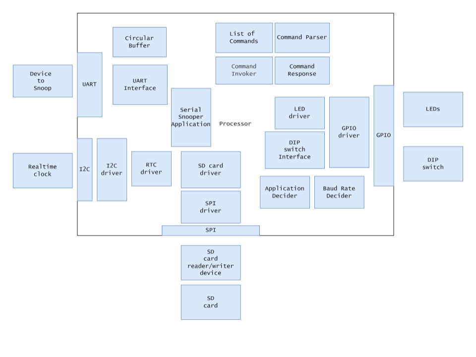
Main components on the Data-Logger-STM32
Data-Logger-STM32 bill of materials (BOM)
76 components, 37 distinct parts — part numbers from the project's BOM.
| Qty | Part | Footprint | Refs |
|---|---|---|---|
| 1 | C43181 74HC4050D,653 | SOIC127P600X175-16N | IC1 |
| 1 | STM32F303K8T6 | LQFP-32_7x7mm_P0.8mm | U1 |
| 1 | AMS1117-3.3 | SOT-223-3_TabPin2 | U2 |
| 1 | MAX3232 | SOIC-16_3.9x9.9mm_P1.27mm | U3 |
| 1 | PCF8523T | SOIC-8_3.9x4.9mm_P1.27mm | U4 |
| 1 | MMBT3904 | SOT-23 | Q1 |
| 1 | MMBT3906 | SOT-23 | Q2 |
| 1 | 16MHZ 16MHz | Crystal_SMD_3225-4Pin_3.2x2.5mm | Y1 |
| 1 | 32.768 | Crystal_SMD_2012-2Pin_2.0x1.2mm | Y2 |
| 1 | CONN_01X03_PIN Conn_01x03_Pin | PinHeader_1x03_P2.54mm_Vertical_SMD_Pin1Left | J1 |
| 1 | CONN_01X05_PIN Conn_01x05_Pin | PinHeader_1x05_P2.54mm_Vertical_SMD_Pin1Left | J2 |
| 1 | L717SDE09P1ACH | L717SDE09P1ACH | J5 |
| 1 | MICRO_SD_CARD_DET1 Micro_SD_Card_Det1 | 5025700893 | J6 |
| 1 | C428494 USB_B_Mini | USB-MINI-10033526-N3212LF | J8 |
| 1 | 0ZCK0020FF2G | FUSC2214X100N | F2 |
| 4 | MountingHole | ToolingHole | H1, H2, H3, H4 |
| 1 | 2894 | 2894 | H5 |
| 1 | SW_DIP_X04 SW_DIP_x04 | SW_DIP_SPSTx04_Slide_Omron_A6H-4101_W6.15mm_P1.27mm | SW1 |
| 1 | SW_DPDT_X2 SW_DPDT_x2 | DPDT-SMD-MS-22D28G2-B | SW2 |
| 1 | GREEN | LED_0603_1608Metric | D1 |
Show 17 more
| Qty | Part | Footprint | Refs |
|---|---|---|---|
| 1 | RED | LED_0603_1608Metric | D3 |
| 1 | RED_SD | LED_0603_1608Metric | D4 |
| 1 | YELLOW | LED_0603_1608Metric | D5 |
| 1 | 120R | L_0603_1608Metric | FB1 |
| 1 | 10N 10n | C_0402_1005Metric | C1 |
| 2 | 1u | C_0402_1005Metric | C2, C3 |
| 11 | 100N 100n | C_0402_1005Metric | C4, C5, C6, C7, C12, C13, C14, C16 +3 |
| 2 | 15P 15p | C_0402_1005Metric | C8, C9 |
| 2 | 22U 22u | C_0805_2012Metric | C10, C11 |
| 3 | 10U 10u | C_0603_1608Metric | C15, C20, C21 |
| 7 | 10K | R_0402_1005Metric | R1, R3, R4, R5, R6, R21, R22 |
| 5 | 1K5 1k5 | R_0402_1005Metric | R2, R12, R18, R23, R26 |
| 2 | DNP | R_0402_1005Metric | R7, R10 |
| 2 | 330R | R_0402_1005Metric | R8, R27 |
| 1 | 0R | R_0805_2012Metric | R9 |
| 4 | 0R | R_0402_1005Metric | R11, R24, R25, R28 |
| 7 | 47K 47k | R_0402_1005Metric | R13, R14, R15, R16, R17, R19, R20 |
Data-Logger-STM32 design files
The KiCad project lives in the can-caglar/Data-Logger-STM32 repository on GitHub; these links point at the commit this page was built from.
Data-Logger-STM32: common questions
What microcontroller does the Data-Logger-STM32 use?
The Data-Logger-STM32 is built around the STM32F303K8T6, from the STM32 family.
How big is the Data-Logger-STM32 PCB?
The Data-Logger-STM32 measures 104 × 43.3 mm, has 2 copper layers and is 2.63 mm thick.
How many components are on the Data-Logger-STM32?
76 components, from 37 distinct parts, with part numbers taken from the project's own BOM. The full bill of materials is listed on this page.
Where can I download the Data-Logger-STM32 design files?
From the can-caglar/Data-Logger-STM32 repository on GitHub, which has the KiCad layout, the schematic and the BOM; the links under Design files point to each one.
Can I use the Data-Logger-STM32 design in my own project?
The repository has no license, so all rights stay with can-caglar. Use it as a reference, and ask the author before reusing the design.
Can I test firmware for the Data-Logger-STM32 without the hardware?
Yes. HardLabs builds a simulation of the board from its netlist and BOM, so you can run and debug STM32 firmware against it before you order a PCB.
Similar boards
 STM32
LumenPnP Motherboard
opulo-inc
149 × 95 mm296 parts4LCC-BY-SA-4.03.7k STM32
Type g
google
169 × 30 mm24 parts2LApache-2.02.9k STM32
Main panel
234 × 84 mm26 parts4LApache-2.02.9k STM32
Base
52.3 × 52.3 mm36 parts2LApache-2.02.9k STM32
Type a
150 × 30 mm14 parts2LApache-2.02.9k STM32
Type c
188 × 30 mm17 parts2LApache-2.02.9k