
QMTechBaseBoard

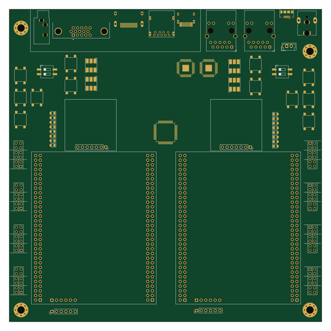
About the QMTechBaseBoard PCB
QMTechBaseBoard is an open source PCB design by carlosedp, published on GitHub under the MIT license. It is a 2-layer board measuring 170 × 170 mm, with 64 components from 21 distinct parts.
Other key parts include the FT4232H and RTL8211EG-VB-CG. By type, the board carries 20 diodes, 16 connectors, 14 switches and 3 ICs.
It belongs with the usb & debug tools designs in this gallery.
From the project
BaseBoard design for QMTech Kintex 7 FPGA
The objective of this project is to design a standard-size motherboard, initially in Mini-ITX size, to host dual Kintex 7 core boards from QMTech and sold thru AliExpress.
The QMTechBaseBoard directory hosts Kicad files for the board design. We are still in draft phase and plan to close the design once the desired (and possible) peripherals have been defined.
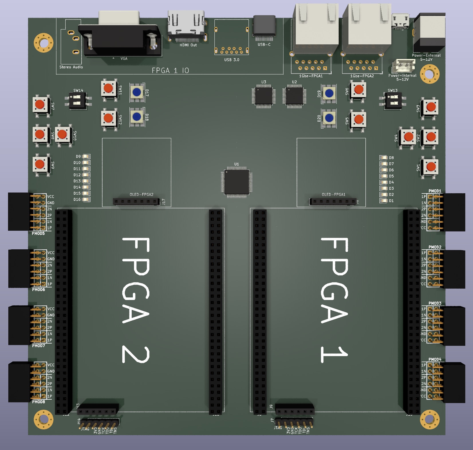
Main components on the QMTechBaseBoard
QMTechBaseBoard bill of materials (BOM)
64 components, 21 distinct parts.
| Qty | Part | Footprint | Refs |
|---|---|---|---|
| 1 | FT4232H | LQFP-64_10x10mm_P0.5mm | U1 |
| 2 | RTL8211EG-VB-CG | LQFP-48-1EP_7x7mm_P0.5mm_EP3.6x3.6mm | U2, U3 |
| 1 | OLED-FPGA1 | PinSocket_1x07_P2.54mm_Vertical | J1 |
| 1 | Stereo Audio | Jack_3.5mm_CUI_SJ1-3533NG_Horizontal | J3 |
| 1 | Power-Internal | JST_EH_B2B-EH-A_1x02_P2.50mm_Vertical | J5 |
| 1 | Power-External | BarrelJack_CUI_PJ-063AH_Horizontal | J6 |
| 1 | JTAG-FPGA1 | PinHeader_1x06_P2.54mm_Vertical | J7 |
| 4 | Conn_02x32_Odd_Even | PinSocket_2x32_P2.54mm_Vertical | J8, J10, J12, J16 |
| 2 | Conn_01x06_Female | PinSocket_1x06_P2.54mm_Vertical | J9, J13 |
| 2 | Micro_SD_Card | microSD_HC_Wuerth_693072010801 | J11, J15 |
| 1 | JTAG-FPGA2 | PinHeader_1x06_P2.54mm_Vertical | J14 |
| 1 | OLED-FPGA2 | PinSocket_1x07_P2.54mm_Vertical | J17 |
| 1 | UART-JTAG | USB_Micro-B_Amphenol_10118194_Horizontal | J21 |
| 1 | 1Gbe-FPGA1 | RJ45_Wuerth_7499111446_Horizontal | 1Gbe-FPGA1 |
| 1 | 1Gbe-FPGA2 | RJ45_Wuerth_7499111446_Horizontal | 1Gbe-FPGA2 |
| 8 | PMOD-Host-x2-GPIO | pmod_pin_array_6x2_hs | PMOD1, PMOD2, PMOD3, PMOD4, PMOD5, PMOD6, PMOD7, PMOD8 |
| 12 | SW_Push | SW_SPST_PTS645 | SW1, SW2, SW3, SW4, SW5, SW6, SW7, SW8 +4 |
| 2 | SW_DIP_x02 | SW_DIP_SPSTx02_Slide_6.7x6.64mm_W8.61mm_P2.54mm_LowProfile | SW13, SW14 |
| 1 | USB3_A | USB3_A_Molex_48393-001 | USB 3.0 |
| 16 | LED | LED_0805_2012Metric_Pad1.15x1.40mm_HandSolder | D1, D2, D3, D4, D5, D6, D7, D8 +8 |
Show 1 more
| Qty | Part | Footprint | Refs |
|---|---|---|---|
| 4 | LED_ABGR | LED_RGB_Cree-PLCC-6_6x5mm_P2.1mm | D17, D18, D19, D20 |
QMTechBaseBoard design files
The KiCad project lives in the carlosedp/QMTechBaseBoard repository on GitHub; these links point at the commit this page was built from.
QMTechBaseBoard: common questions
How big is the QMTechBaseBoard PCB?
The QMTechBaseBoard measures 170 × 170 mm, has 2 copper layers and is 1.6 mm thick.
How many components are on the QMTechBaseBoard?
64 components, from 21 distinct parts. The full bill of materials is listed on this page.
Where can I download the QMTechBaseBoard design files?
From the carlosedp/QMTechBaseBoard repository on GitHub, which has the KiCad layout and the schematic; the links under Design files point to each one.
Can I use the QMTechBaseBoard design in my own project?
Yes, under the terms of its MIT license, which carlosedp chose for the repository.
Similar boards
XG Station Power
osy
54.3 × 91 mm9 parts2LCC-BY-4.0703
USB Hub Test
50 × 50 mm85 parts4LCC-BY-4.0703
FW-EC-DongleHiderPlus
LeoDJ
28.2 × 26.1 mm14 parts4LCERN-OHL-W-2.0490
Adapter tsop48
bbogush
48 × 33 mm3 parts2LGPL-3.0389
Adapter tsop48 solder
48 × 33 mm3 parts2LGPL-3.0389
Adapter soic8 solder
48 × 20 mm3 parts2LGPL-3.0389