Gain box amp

About the Gain box amp PCB
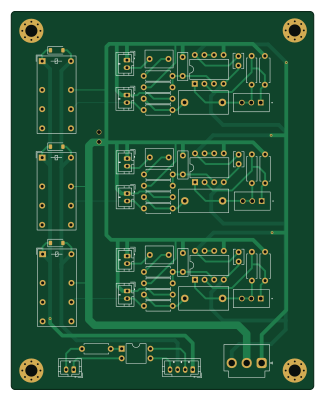
Gain box amp is an open source PCB design by carmisergio, published on GitHub. It is a 2-layer board measuring 80 × 100 mm, with 53 components from 16 distinct parts.
Other key parts include the NE5532 and 140817141310. By type, the board carries 19 resistors, 12 capacitors, 9 connectors, 4 ICs, 3 relays and 3 diodes.
From the project
PCB designs and firmware for the Denon AVR-X1300W Pre-out mod
The scope of this project is adding line-level outputs to the Denon AVR-X1300W AV Receiver. This can be acheived by getting the low-level signals from the digital board of the receiver before they make their way to the power amp board.
The "Vampire PCB" is soldered directly to the digital board of the receiverr, and provides an 8-pin JST PH connector with the signals. A small length of shielded cable brings them to the back panel of the unit, where removing the AM/FM tuner unit provides a convenient place to mount a miniature circular connector.
Main components on the Gain box amp
Gain box amp bill of materials (BOM)
53 components, 16 distinct parts.
| Qty | Part | Footprint | Refs |
|---|---|---|---|
| 3 | NE5532 | DIP-8_W7.62mm | U1, U2, U3 |
| 1 | 140817141310 | DIP-4_W7.62mm | U4 |
| 7 | Conn_01x02 | JST_PH_B2B-PH-K_1x02_P2.00mm_Vertical | J1, J2, J3, J4, J5, J6, J7 |
| 1 | Conn_01x03 | JST_VH_B3P-VH-B_1x03_P3.96mm_Vertical | J8 |
| 1 | Conn_01x04 | JST_PH_B4B-PH-K_1x04_P2.00mm_Vertical | J9 |
| 3 | J104D2C12VDC.36S | Relay_DPDT_Finder_30.22 | K1, K2, K3 |
| 3 | 50k | TRIM_PV36W503C01B00 | RV1, RV2, RV3 |
| 3 | SL1B | D_SOD-123 | D1, D2, D3 |
| 3 | 0.68u | C_Rect_L7.2mm_W4.5mm_P5.00mm_FKS2_FKP2_MKS2_MKP2 | C1, C2, C3 |
| 3 | 10n | C_Rect_L7.2mm_W2.5mm_P5.00mm_FKS2_FKP2_MKS2_MKP2 | C4, C5, C6 |
| 3 | 3.3u | C_Rect_L13.0mm_W6.0mm_P10.00mm_FKS3_FKP3_MKS4 | C7, C8, C9 |
| 3 | 100n | C_Disc_D3.8mm_W2.6mm_P2.50mm | C10, C11, C12 |
| 6 | 100 | R_Axial_DIN0207_L6.3mm_D2.5mm_P7.62mm_Horizontal | R1, R2, R3, R4, R5, R6 |
| 3 | 220k | R_Axial_DIN0207_L6.3mm_D2.5mm_P7.62mm_Horizontal | R7, R8, R9 |
| 4 | 2.2k | R_Axial_DIN0207_L6.3mm_D2.5mm_P7.62mm_Horizontal | R10, R11, R12, R19 |
| 6 | 33k | R_Axial_DIN0207_L6.3mm_D2.5mm_P7.62mm_Horizontal | R13, R14, R15, R16, R17, R18 |
Gain box amp design files
The KiCad project lives in the carmisergio/denon-preout-mod repository on GitHub; these links point at the commit this page was built from.
Gain box amp: common questions
How big is the Gain box amp PCB?
The Gain box amp measures 80 × 100 mm, has 2 copper layers and is 1.6 mm thick.
How many components are on the Gain box amp?
53 components, from 16 distinct parts. The full bill of materials is listed on this page.
Where can I download the Gain box amp design files?
From the carmisergio/denon-preout-mod repository on GitHub, which has the KiCad layout and the schematic; the links under Design files point to each one.
Can I use the Gain box amp design in my own project?
The repository has no license, so all rights stay with carmisergio. Use it as a reference, and ask the author before reusing the design.