
131 open source boards using the NE5532
Real designs built with the NE5532, from public GitHub projects: a quick way to see how others power, decouple and connect it. Each board comes with its KiCad files, full parts list and a render — and you can simulate its firmware on HardLabs.
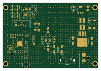
SI4684 SMD
PE5PVB
100 × 68 mm90 parts2LGPL-3.0131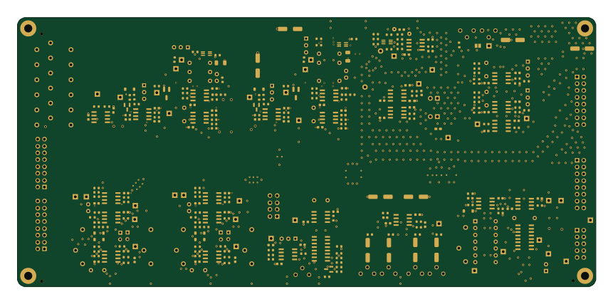
Core
shmoergh
215 × 100 mm285 parts2LNo license124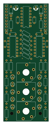
Output
QuinnFreedman
38 × 100 mm124 parts2LNo license114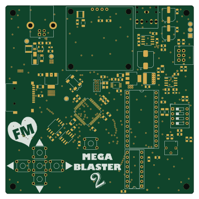 Microchip SAM
MegaBlaster2
AidanHockey5
99 × 99 mm102 parts4LAGPL-3.059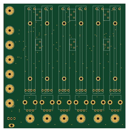
Sk162-herd mixer
mirdej
104.3 × 106.8 mm223 parts4LNo license47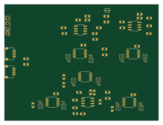
Digishaper152
jonnor
80 × 60 mm60 parts2LNo license43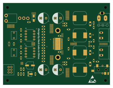
Hack amp
hack-apollo
99.5 × 75.9 mm73 parts2LGPL-3.037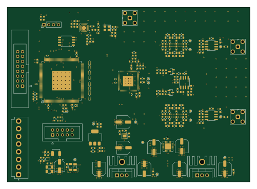 FPGA
Analog board
EERNINUO
125 × 90 mm281 parts4LGPL-3.036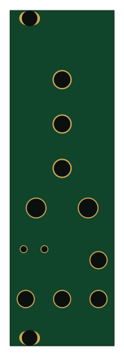
Multi saturation module
DIYSynthMNL
40 × 128.5 mm63 parts2LGPL-3.023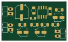
Electret preamp
dunkelstern
34 × 20.5 mm16 parts2LNo license14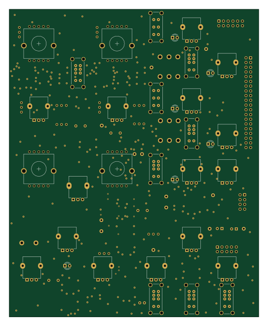
MICRO-OX Main VCO board
JordanAceto
133.9 × 165.1 mm280 parts4LCC-BY-4.08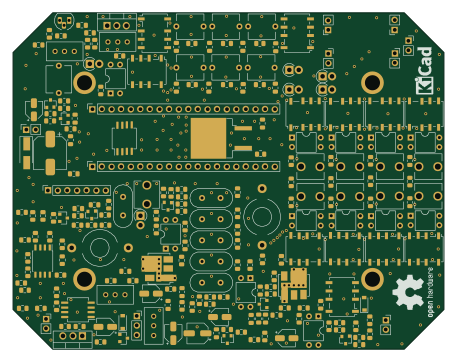
Ayn-4b
afiskon
114 × 89 mm272 parts2LMIT6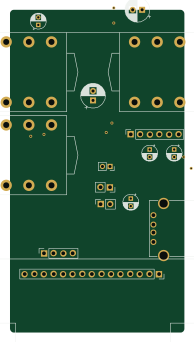
Pangaea cp16
ildus
46.2 × 85.5 mm77 parts2LNo license6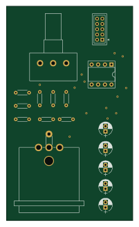
Mic-Preamp
naufalboys
48.3 × 81.3 mm10 parts2LGPL-3.06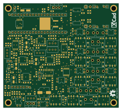
Ayn dc
100 × 90 mm220 parts2LMIT5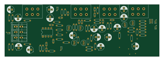
Mixer analog DJB3
thomasrPPS
140 × 47 mm90 parts2LNo license4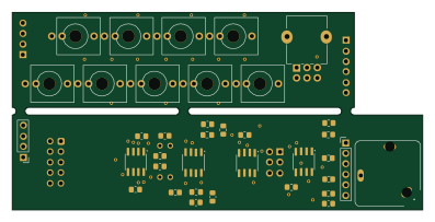
Exits-1U
benregnier
99.1 × 47.7 mm70 parts2LNo license4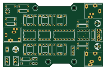
Electronic-Stethescope
shreenandansonu
85 × 55 mm54 parts2LMIT3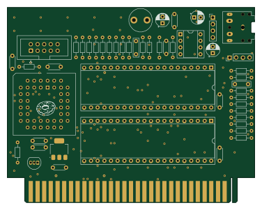
TS Ext EPM3032
ponchick
94 × 74.3 mm50 parts2LNo license3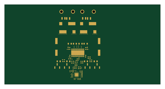 TI MSP430/CC
Projet Sound Bar DIY
HodearS
165.7 × 85 mm799 parts4LNo license2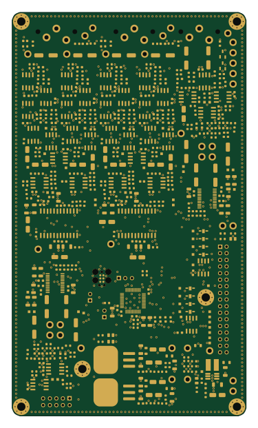 STM32
Audio daughterboard
Jaxc
90 × 155 mm453 parts4LGPL-3.02
DMH Output PCB 1
DeMarco
48 × 175 mm263 parts2LCC0-1.02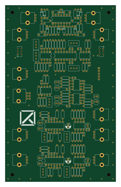
AnalogDrum Metal
LazareLive
100.3 × 160 mm172 parts2LNo license2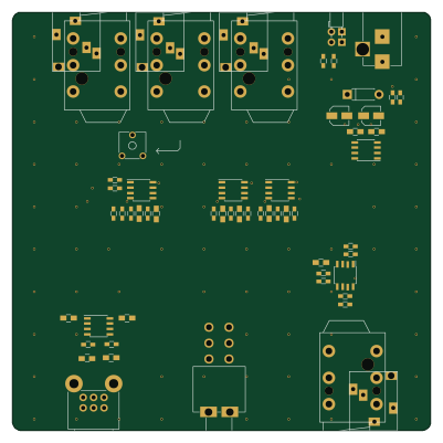
Athena
JanKoppe
100 × 100 mm123 parts2LNo license2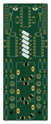
Output
nathanaelnoir
38 × 100 mm121 parts2LMIT2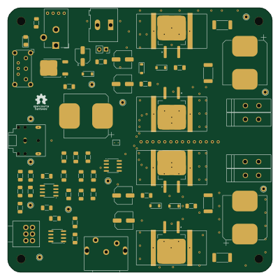
Class AB Stereo Amp SMD
alexandrebobkov
100 × 100 mm78 parts2LMIT2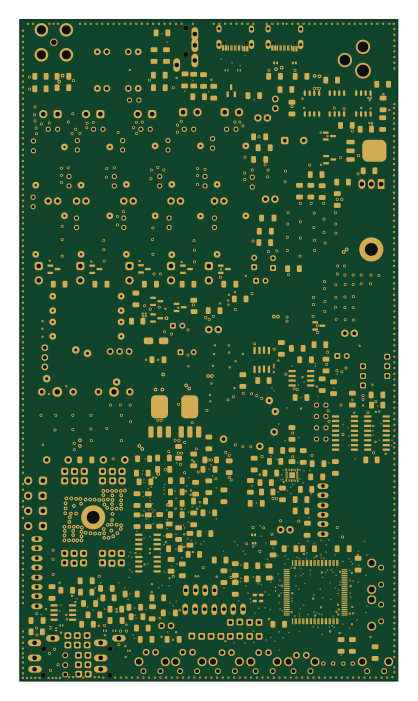 STM32
Spartacus PCB REV1
vpcsln
100 × 175 mm436 parts6LNo license1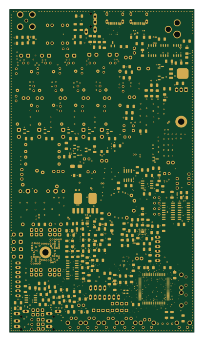 STM32
Spartacus PCB REV1
spartacus-hf
100 × 175 mm436 parts6LCERN-OHL-S-2.01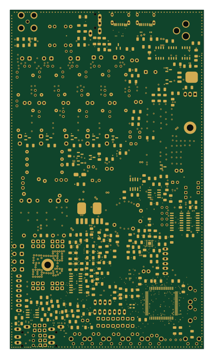 STM32
Chireix
100 × 175 mm435 parts6LNo license1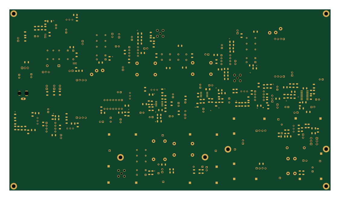
Phoenix612 Complete v1.1
drajnauth
281.2 × 158.6 mm283 parts2LCC-BY-NC-4.01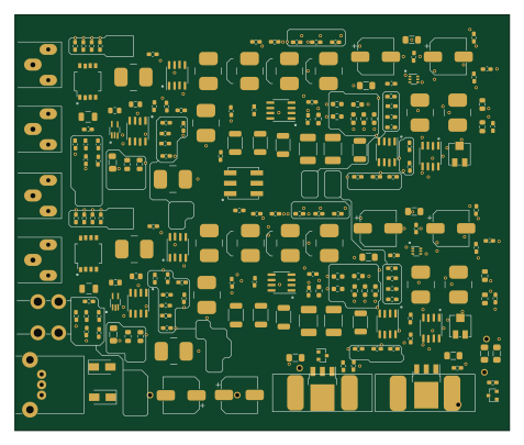
Actidamp mk4-smd
josko7452
119 × 100 mm199 parts4LNo license1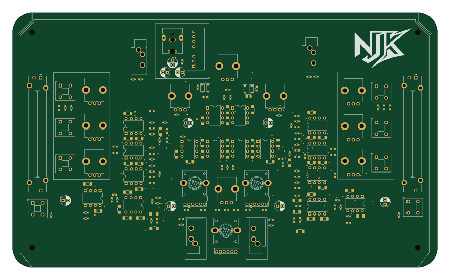
Analog mixer
nehajaykul
219.5 × 131.5 mm196 parts2LNo license1
Basic Stereo Amp v3
halherta
100 × 100 mm74 parts2LNo license1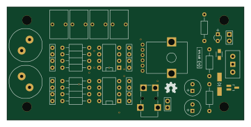
EMLD
UEPro
90 × 43 mm38 parts2LNo license1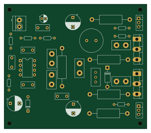
Diamond buffer amp
prydin
76.5 × 66.3 mm36 parts2LNo license1- schematic only · 98 parts
Meyer Sound 24.033.003 Amp RevEng
LeoDJ
98 partsNo license1
How designs wire the NE5532
Read from the KiCad layouts of 92 open source designs, one per repository: what each pin of the NE5532 connects to, and the resistors, capacitors and other passives placed on it.
- The - pins have a series resistor on 81 of 92 designs, most often 10 kΩ (then 1 kΩ).
- The A_OUTPUT pin has a series resistor on 70 of 92 designs, most often 10 kΩ (then 1 kΩ).
- The B_OUTPUT pin has a series resistor on 60 of 91 designs, most often 10 kΩ (then 100 Ω).
- The V+ pin has a decoupling capacitor on 60 of 91 designs, most often 100 nF (then 10 µF).
| Pin | Connected to | Parts on the pin |
|---|---|---|
| A_OUTPUTpin 1 | Connected to: Signal 91% |
|
| -pin 2, 6 | Connected to: Signal 88% |
|
| +pin 3, 5 | Connected to: Signal 78% |
|
| V-pin 4 | Connected to: GND 46% · -12V 40% |
|
| B_OUTPUTpin 7 | Connected to: Signal 84% |
|
| V+pin 8 | Connected to: 12V 84% · a signal 15% |
|
Connections count pins, parts count designs; values in brackets are how many parts had that value. Designs read include Utils output core by shmoergh, SI4684 by PE5PVB, Core by shmoergh and Output by QuinnFreedman.
The NE5532 in open source designs
The gallery holds 131 open source boards using the NE5532 from 94 GitHub repositories; a typical one measures about 98.7 × 91.1 mm and carries around 96 components.
74% are two-layer designs, the rest use four layers or more, and 34% carry an open source license.
The most starred is Utils output core by shmoergh.
Parts used alongside the NE5532
Microcontrollers on boards using the NE5532
What boards using the NE5532 are built for
NE5532: common questions
Where can I find a NE5532 reference design?
Each of the 131 boards on this page is a real design using the NE5532. Open one to see how it is wired up, with the full BOM, a render of the layout and links to its KiCad files.
What resistor goes on the NE5532 - pin?
The - pins have a series resistor on 81 of 92 designs, most often 10 kΩ (then 1 kΩ). Counted from the KiCad layouts of 92 open source designs using the NE5532.
What resistor goes on the NE5532 A_OUTPUT pin?
The A_OUTPUT pin has a series resistor on 70 of 92 designs, most often 10 kΩ (then 1 kΩ). Counted from the KiCad layouts of 92 open source designs using the NE5532.
What resistor goes on the NE5532 B_OUTPUT pin?
The B_OUTPUT pin has a series resistor on 60 of 91 designs, most often 10 kΩ (then 100 Ω). Counted from the KiCad layouts of 92 open source designs using the NE5532.
What parts are used alongside the NE5532?
The TL072, TL074, L7805, LM339 and AMS1117-3.3 appear in the most repositories here.
Which microcontrollers do boards using the NE5532 use?
Most are built on STM32 (11), AVR/Arduino (5), RP2040/RP2350 (3) and FPGA (2).
How big is a typical board using the NE5532?
The median is 98.7 × 91.1 mm, and 74% are two-layer designs.
What is the most popular open source board using the NE5532?
By GitHub stars, Utils output core by shmoergh, with 219 stars.
Can I simulate one of these boards using the NE5532 before building it?
Yes. HardLabs turns a board's netlist and BOM into a working simulation, so you can boot and test firmware against it with no hardware on your desk.