
Radar MCU

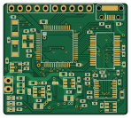
About the Radar MCU PCB
Radar MCU is an open source STM32 PCB design by ckflight, published on GitHub under the GPL-3.0 license. It is a 4-layer board measuring 36.9 × 32.9 mm, with 98 components from 35 distinct parts.
Its main chip is the STM32F405, from the STM32 family. Other key parts include the AP3211, LP2985_10, MCP4022_202, LT1817 and MAX1426. By type, the board carries 44 capacitors, 34 resistors, 7 ICs, 4 connectors, 2 transistors and 2 diodes.
It belongs with the audio designs in this gallery.
From the project
Frequency Modulated Continuous Wave Radar hardware and software design files with 26 dBm output power covering around 250 m.
Check the new design's Python files for better processing and analysis https://github.com/ckflight/FMCWRADAR2v2
$$ Range(radar) = {\sqrt[4]{Pt G^2 \lambda^2 \sigma \over Pmin 4\pi^3}} $$
* Receiver chain has LNA, Gain Block and Mixer. The gain block drops the Noise Figure from 7 dB to 2 dB, which doubles the detection range. To determine the radar detection range, minimum detectable signal is needed. RF receiver chain has thermal noise and it determines the noise floor for Pmin. Signal to Noise (SNR) ratio of 20 dB is assumed for a good detectable signal then:

Main components on the Radar MCU
Radar MCU bill of materials (BOM)
98 components, 35 distinct parts.
| Qty | Part | Footprint | Refs |
|---|---|---|---|
| 2 | AP3211 | SOT23_6 | U1, U2 |
| 1 | LP2985_10 | SOT23_5 | U3 |
| 1 | STM32F405 | LQFP64_10x10mm_P0.5mm | U4 |
| 1 | MCP4022_202 | SOT23_6 | U7 |
| 1 | LT1817 | SSOP16_3.9x4.9mm_P0.635mm | U8 |
| 1 | MAX1426 | SSOP28_5.3x10.2mm_P0.65mm | U9 |
| 2 | BSS138 | SOT23_3 | Q1, Q2 |
| 1 | 8MHz | Crystal_3.2x2.5mm | Y1 |
| 1 | SWD_DEBUGGER | PinHeader_1x5_P2.54mm | J1 |
| 1 | USB_MicroB | USB_MicroB_TH | J3 |
| 1 | Connector_02x15 | PinHeader_2x15_DF12B(5.0)-30DP-0.5V(86) | J4 |
| 1 | GPIO_EXTRA | PinHeader_1x5_P2.54mm | J5 |
| 2 | Led_Diode | Diode_0603 | 3V3, 5V |
| 2 | SDM2U30CSP_7 | Diode_SDM2U30CSP_7 | D1, D2 |
| 2 | 4.7uH | SMD_0805 | L1, L2 |
| 4 | 10uF | SMD_0603 | C1, C2, C15, C28 |
| 5 | 22uF | SMD_0603 | C3, C6, C9, C43, C44 |
| 3 | 10nF | SMD_0402 | C4, C7, C10 |
| 7 | 2.2uF | SMD_0402 | C5, C11, C16, C17, C19, C20, C29 |
| 17 | 100nF | SMD_0402 | C8, C12, C13, C14, C18, C23, C24, C26 +9 |
Show 15 more
| Qty | Part | Footprint | Refs |
|---|---|---|---|
| 2 | 15pF | SMD_0402 | C21, C22 |
| 2 | 33pF | SMD_0402 | C25, C38 |
| 2 | 100pF | SMD_0402 | C32, C33 |
| 2 | 1uF | SMD_0402 | C39, C40 |
| 3 | 22 | SMD_0402 | R1, R2, R16 |
| 1 | 14.7K | SMD_0402 | R3 |
| 4 | 4.7K | SMD_0402 | R4, R23, R27, R31 |
| 3 | 100 | SMD_0402 | R5, R6, R22 |
| 6 | 10K | SMD_0402 | R7, R8, R17, R24, R28, R29 |
| 3 | 0 | SMD_0402 | R9, R10, R26 |
| 3 | DNP | SMD_0402 | R11, R12, R25 |
| 7 | 1K | SMD_0402 | R13, R14, R18, R20, R32, R33, R34 |
| 2 | 2.49K | SMD_0402 | R15, R19 |
| 1 | 49.9 | SMD_0402 | R21 |
| 1 | 24.4K | SMD_0402 | R30 |
Radar MCU design files
The KiCad project lives in the ckflight/FMCW-RADAR repository on GitHub; these links point at the commit this page was built from.
Radar MCU: common questions
What microcontroller does the Radar MCU use?
The Radar MCU is built around the STM32F405, from the STM32 family.
How big is the Radar MCU PCB?
The Radar MCU measures 36.9 × 32.9 mm, has 4 copper layers and is 1.6 mm thick.
How many components are on the Radar MCU?
98 components, from 35 distinct parts. The full bill of materials is listed on this page.
Where can I download the Radar MCU design files?
From the ckflight/FMCW-RADAR repository on GitHub, which has the KiCad layout; the links under Design files point to each one.
Can I use the Radar MCU design in my own project?
Yes, under the terms of its GPL-3.0 license, which ckflight chose for the repository.
Can I test firmware for the Radar MCU without the hardware?
Yes. HardLabs builds a simulation of the board from its netlist and BOM, so you can run and debug STM32 firmware against it before you order a PCB.
More boards in FMCW-RADAR
Similar boards
 STM32
STM32LumenPnP Motherboard
opulo-inc
149 × 95 mm296 parts4LCC-BY-SA-4.03.7k STM32
STM32AxxSolder
AxxAxx
39 × 82.5 mm122 parts2LGPL-3.01.7k STM32
STM32AIOC
skuep
21 × 31.5 mm47 parts2LMIT1.4k STM32
STM32Ferris
pierrechevalier83
208.8 × 86.8 mm102 parts2LSHL-2.11.3k STM32
STM32176 pin board
rusefi
61.8 × 73.2 mm76 parts2LGPL-3.01.2k STM32
STM32Brain board STM32F407
61.8 × 73.2 mm69 parts2LGPL-3.01.2k