
Radar RF

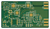
About the Radar RF PCB
Radar RF is an open source PCB design by ckflight, published on GitHub under the GPL-3.0 license. It is a 4-layer board measuring 42.9 × 24.5 mm, with 138 components from 55 distinct parts.
Other key parts include the LT6232, ADF4158, SG-210STF, MITERED_BEND and 5400BL15B050E. By type, the board carries 64 capacitors, 42 resistors, 23 ICs, 5 inductors and 1 connector.
It belongs with the audio designs in this gallery.
From the project
Frequency Modulated Continuous Wave Radar hardware and software design files with 26 dBm output power covering around 250 m.
Check the new design's Python files for better processing and analysis https://github.com/ckflight/FMCWRADAR2v2
$$ Range(radar) = {\sqrt[4]{Pt G^2 \lambda^2 \sigma \over Pmin 4\pi^3}} $$
* Receiver chain has LNA, Gain Block and Mixer. The gain block drops the Noise Figure from 7 dB to 2 dB, which doubles the detection range. To determine the radar detection range, minimum detectable signal is needed. RF receiver chain has thermal noise and it determines the noise floor for Pmin. Signal to Noise (SNR) ratio of 20 dB is assumed for a good detectable signal then:

Main components on the Radar RF
Radar RF bill of materials (BOM)
138 components, 55 distinct parts.
| Qty | Part | Footprint | Refs |
|---|---|---|---|
| 1 | LT6232 | SSOP16_3.9x4.9mm_P0.635mm | U1 |
| 1 | ADF4158 | LFCSP24_4x4mm_P0.5mm_1EXP_2.5x2.5mm | U2 |
| 1 | SG-210STF | Crystal_2.5x2mm | U3 |
| 3 | MITERED_BEND | Mitered_Bend_0.34mm_90 | U4, U9, U23 |
| 1 | MITERED_BEND | Mitered_Bend_0.34mm_45 | U5 |
| 2 | 5400BL15B050E | Balun_5400BL15B050E | U6, U13 |
| 1 | TLV172 | SC70_5 | U7 |
| 1 | MITERED_BEND | Mitered_Bend_0.34mm_45_Mirrored | U8 |
| 1 | ADL5801 | LFCSP24_4x4mm_P0.5mm_1EXP_2.5x2.5mm | U10 |
| 1 | HMC431LP4 | QFN24_4x4mm_P0.5mm_1EXP_2.7x2.7mm | U11 |
| 1 | LDS3985 | SOT23_5 | U12 |
| 2 | PAT1220-C-6DB | PAT1220_6dB | U14, U19 |
| 1 | TRF37A73 | WSON8_2x2mm_P0.5mm_1EXP_0.9x1.6mm | U15 |
| 1 | TQP5523 | QFN20_4x4mm_P0.5mm_1EXP_2.5x2.5mm | U16 |
| 1 | MCP1700 | SOT23_3 | U17 |
| 1 | SKY65404 | SKY65404_31 | U18 |
| 1 | Directional_Coupler | Directional_Coupler_15dB | U20 |
| 2 | SMA_Connector | SMA_Connector | U21, U22 |
| 1 | Connector_02x15 | PinHeader_2x15_DF12B(5.0)-30DP-0.5V(86) | J1 |
| 3 | Led_Diode | Diode_0603 | 3V0, 3V3, 5V |
Show 35 more
| Qty | Part | Footprint | Refs |
|---|---|---|---|
| 2 | 2.2uH | SMD_0603 | L1, L2 |
| 1 | BLM18PG181SN1D | SMD_0603 | L3 |
| 1 | LQW15AN9N9J80D | SMD_0402 | L4 |
| 1 | 0.6nH | SMD_0402 | L5 |
| 23 | 100nF | SMD_0402 | C12, C13, C14, C21, C22, C28, C37, C38 +15 |
| 5 | 18pF | SMD_0402 | C15, C16, C18, C59, C68 |
| 1 | 2.2nF | SMD_0402 | C17 |
| 3 | 330nF | SMD_0402 | C19, C20, C26 |
| 5 | 100pF | SMD_0402 | C23, C41, C42, C47, C65 |
| 7 | 10pF | SMD_0402 | C24, C25, C35, C36, C54, C55, C62 |
| 1 | 2pF | SMD_0402 | C27 |
| 6 | 470pF | SMD_0402 | C29, C31, C32, C33, C34, C44 |
| 3 | 10nF | SMD_0402 | C30, C56, C61 |
| 4 | 2.2uF | SMD_0402 | C49, C57, C63, C71 |
| 2 | DNP | SMD_0402 | C58, C66 |
| 2 | 1000pF | SMD_0402 | C60, C72 |
| 1 | 10uF | SMD_0603 | C70 |
| 1 | 0.5pF | SMD_0402 | C73 |
| 7 | 1K | SMD_0402 | R1, R16, R19, R29, R39, R40, R42 |
| 4 | DNP | SMD_0402 | R2, R3, R15, R30 |
| 5 | 0 | SMD_0402 | R4, R12, R22, R35, R43 |
| 2 | 549 | SMD_0402 | R5, R6 |
| 1 | 5.49K | SMD_0402 | R7 |
| 1 | 69.8 | SMD_0402 | R8 |
| 3 | 10K | SMD_0402 | R9, R10, R34 |
| 1 | 240 | SMD_0402 | R11 |
| 2 | 910 | SMD_0402 | R13, R14 |
| 2 | 130 | SMD_0402 | R17, R18 |
| 2 | 4.99K | SMD_0402 | R20, R21 |
| 3 | 4.7K | SMD_0402 | R23, R24, R26 |
| 3 | 50 | SMD_0402 | R25, R28, R41 |
| 3 | 18 | SMD_0402 | R31, R32, R33 |
| 1 | 0 to 27 | SMD_0402 | R36 |
| 1 | 30K | SMD_0402 | R37 |
| 1 | 100 | SMD_0402 | R38 |
Radar RF design files
The KiCad project lives in the ckflight/FMCW-RADAR repository on GitHub; these links point at the commit this page was built from.
Radar RF: common questions
How big is the Radar RF PCB?
The Radar RF measures 42.9 × 24.5 mm, has 4 copper layers and is 1.6 mm thick.
How many components are on the Radar RF?
138 components, from 55 distinct parts. The full bill of materials is listed on this page.
Where can I download the Radar RF design files?
From the ckflight/FMCW-RADAR repository on GitHub, which has the KiCad layout; the links under Design files point to each one.
Can I use the Radar RF design in my own project?
Yes, under the terms of its GPL-3.0 license, which ckflight chose for the repository.
More boards in FMCW-RADAR
Similar boards
KLOR
GEIGEIGEIST
160.2 × 118.3 mm79 parts2LGPL-3.01.2k
ButtonsLEDs
shanteacontrols
390 × 37 mm82 parts2LApache-2.0956
USB
52 × 12.6 mm6 parts2LApache-2.0956
Pots
390 × 93 mm75 parts2LApache-2.0956
PicoGUS Hand386
polpo
29.2 × 75.2 mm43 parts4LGPL-2.0800
Snark barker
schlae
231.1 × 106.7 mm193 parts2LNo license687