
Servo-Tester

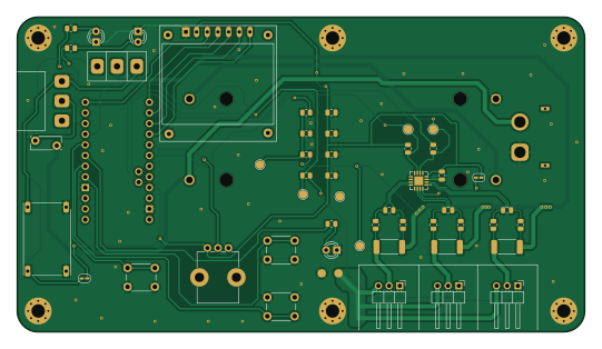
About the Servo-Tester PCB
Servo-Tester is an open source PCB design by CodeWorksCZ, published on GitHub under the MIT license. It is a 2-layer board measuring 135 × 75 mm, with 45 components from 31 distinct parts.
Other key parts include the MINI360, INA3221 and Clone_Pro_Mini_Socket. By type, the board carries 18 resistors, 8 capacitors, 5 switches, 4 connectors, 3 diodes and 2 ICs.
It belongs with the robotics & motion and displays & leds designs in this gallery.
From the project
Arduino Pro Mini RC servo tester with OLED UI, EEPROM settings, and 3-channel INA3221 current/voltage monitoring.
This folder contains schematics/PCB files for the Servo Tester hardware.
- Keep logic rail (VCC for Pro Mini + OLED + INA3221) separate from servo power rail. - Do not feed logic directly from HV servo rail. - Use a common GND, but route high-current servo return separately and join at one star point.
- Add bulk capacitor on servo rail input: 470-1000 uF (low-ESR, voltage rating for your rail). - Add local decoupling near each servo connector: 100 nF from +BATT to GND. - Add TVS diode across servo rail (+BATT to GND) near power entry. - Add PTC fuse in series with servo rail input.
Main components on the Servo-Tester
Servo-Tester bill of materials (BOM)
45 components, 31 distinct parts — part numbers from the project's BOM.
| Qty | Part | Footprint | Refs |
|---|---|---|---|
| 1 | MINI360 Mini360 | Ultra Mini-360 | U1 |
| 1 | INA3221 | INA3221_VQFN-16_4x4mm_P0.65mm_EP2.6x2.6mm | U2 |
| 1 | Clone_Pro_Mini_Socket | Clone_Pro_Mini_Socket_No_PROG | A1 |
| 1 | CONN_01X03_PIN Servo 1 | PinHeader_1x03_P2.54mm_Horizontal | J1 |
| 1 | CONN_01X03_PIN Servo 2 | PinHeader_1x03_P2.54mm_Horizontal | J2 |
| 1 | CONN_01X03_PIN Servo 3 | PinHeader_1x03_P2.54mm_Horizontal | J3 |
| 1 | XT60PW-M | AMASS_XT60PW-M_1x02_P7.20mm_Horizontal | J4 |
| 1 | BK-18650-PC4 | BAT_BK-18650-PC4 | BT1 |
| 1 | Polyfuse 3A | Fuse_LittleFuseRUEF300 | F1 |
| 1 | 10K | Potentiometer_Bourns_PTV09A-1_Single_Vertical | RV1 |
| 1 | SS-12DXX | SS12D11 | SW1 |
| 1 | SS-12DXX | SS12D10 | SW2 |
| 1 | SW_Push - Up | SW_PUSH_6mm_H8.5mm | SW3 |
| 1 | SW_Push - Select | SW_PUSH_6mm_H8.5mm | SW4 |
| 1 | SW_Push - Down | SW_PUSH_6mm_H8.5mm | SW5 |
| 1 | ~ | OLED_0.96_SPI_Module_1x07_P2.54mm | OLED1 |
| 1 | STD | LED_D3.0mm | D1 |
| 1 | HV | LED_D3.0mm | D2 |
| 1 | ALERT | LED_D3.0mm | D3 |
| 6 | 100nF | C_0805_2012Metric | C1, C2, C5, C6, C7, C8 |
Show 11 more
| Qty | Part | Footprint | Refs |
|---|---|---|---|
| 1 | 0.1uF | C_0805_2012Metric | C3 |
| 1 | 10uF | C_0805_2012Metric | C4 |
| 1 | 47K | R_0805_2012Metric | R1 |
| 1 | 27K | R_0805_2012Metric | R2 |
| 1 | 0R | R_0805_2012Metric | R3 |
| 2 | 1K | R_0805_2012Metric | R4, R5 |
| 1 | 470R | R_0805_2012Metric | R6 |
| 2 | 4K7 | R_0805_2012Metric | R7, R8 |
| 1 | 330R | R_0805_2012Metric | R9 |
| 6 | 10R | R_0805_2012Metric | R10, R11, R12, R13, R14, R15 |
| 3 | 0.1R | R_2512_6332Metric_Pad1.40x3.35mm_HandSolder | R16, R17, R18 |
Servo-Tester design files
The KiCad project lives in the CodeWorksCZ/Servo-Tester repository on GitHub; these links point at the commit this page was built from.
Servo-Tester: common questions
How big is the Servo-Tester PCB?
The Servo-Tester measures 135 × 75 mm, has 2 copper layers and is 1.6 mm thick.
How many components are on the Servo-Tester?
45 components, from 31 distinct parts, with part numbers taken from the project's own BOM. The full bill of materials is listed on this page.
Where can I download the Servo-Tester design files?
From the CodeWorksCZ/Servo-Tester repository on GitHub, which has the KiCad layout, the schematic and the BOM; the links under Design files point to each one.
Can I use the Servo-Tester design in my own project?
Yes, under the terms of its MIT license, which CodeWorksCZ chose for the repository.
Similar boards
BM28B0.6-24DSBreakout
scottbez1
15.2 × 35.6 mm3 parts2LApache-2.022.2k
LevelShifterBreakout
15.2 × 20.3 mm5 parts2LApache-2.022.2k
View base
81.2 × 81.2 mm81 parts2LApache-2.022.2k
View screen
35 × 35 mm12 parts2LApache-2.022.2k
Display eval
byrantech
52.1 × 22.6 mm12 parts4LMIT4.3k
ChainlinkBase
98.4 × 190.5 mm119 parts2LApache-2.04.2k