
Therm temp 4 20 xmtr

About the Therm temp 4 20 xmtr PCB
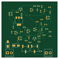
Therm temp 4 20 xmtr is an open source PCB design by ControlSystemIntegrators, published on GitHub under the MIT license. It is a 4-layer board measuring 50 × 50 mm, with 45 components from 24 distinct parts.
Other key parts include the LM4040DBZ-2.5, TL431DBZ and OPA333xxDBV. By type, the board carries 18 resistors, 11 capacitors, 5 transistors, 3 modules, 2 ICs and 1 connector.
It belongs with the sensors and test & measurement designs in this gallery.
From the project
Fully analog 2-wire 4-20 mA NTC thermistor temperature transmitter, built from multi-sourced parts — plus an instrumentation-theory tutorial. Default build: 20-40 C for chocolate temperature control.
A fully analog (no microcontroller) 2-wire 4–20 mA temperature transmitter built from standard, multi-sourced parts — and a worked tutorial in the instrumentation theory behind it.
1. A teaching reference. If you've ever wanted to understand how a 4–20 mA transmitter actually works — loop power, sensor excitation, linearization, zero/span calibration — this is a complete, honest, end-to-end example with the math shown and a calculator you can run. 2. A real instrument. It was designed for chocolate temperature control (the 20–40 °C tempering/working range), as a more accurate and more robust…
Main components on the Therm temp 4 20 xmtr
Therm temp 4 20 xmtr bill of materials (BOM)
45 components, 24 distinct parts — part numbers from the project's BOM.
| Qty | Part | Footprint | Refs |
|---|---|---|---|
| 1 | LM4040DBZ-2.5 | SOT-23 | U1 |
| 1 | TL431DBZ | SOT-23 | U2 |
| 3 | OPA333xxDBV | SOT-23-5 | A1, A2, A3 |
| 2 | MMBT3904 | SOT-23 | Q1, Q3 |
| 1 | BCP56 | SOT-223-3_TabPin2 | Q2 |
| 2 | MMBT3906 | SOT-23 | Q4, Q5 |
| 1 | 3.5mm | ScrewTerminal_1x02_P3.5mm_Horizontal_Black | J1 |
| 2 | 50k | Potentiometer_Bourns_3269W_Vertical | RV1, RV2 |
| 1 | 3.5mm | ScrewTerminal_1x02_P3.5mm_Horizontal_Black | TB1 |
| 1 | SMAJ33A | D_SMA | TVS1 |
| 1 | SS14 | D_SMA | D1 |
| 6 | 100nF | C_0603_1608Metric | C1, C5, C7, C9, C10, C11 |
| 2 | 1uF | C_0603_1608Metric | C2, C8 |
| 1 | 100pF | C_0603_1608Metric | C3 |
| 1 | 1nF | C_0603_1608Metric | C4 |
| 1 | 10nF | C_0603_1608Metric | C6 |
| 1 | 6.04k | R_0603_1608Metric | R1 |
| 3 | 2.49k | R_0603_1608Metric | R2, R7, R15 |
| 3 | 10k | R_0603_1608Metric | R3, R4, R6 |
| 6 | 100k | R_0603_1608Metric | R5, R9, R10, R13, R14, R18 |
Show 4 more
| Qty | Part | Footprint | Refs |
|---|---|---|---|
| 1 | 2k | R_0603_1608Metric | R8 |
| 2 | 249k | R_0603_1608Metric | R11, R12 |
| 1 | 49.9 | R_0603_1608Metric | R16 |
| 1 | 432 | R_0603_1608Metric | R17 |
Therm temp 4 20 xmtr design files
The KiCad project lives in the ControlSystemIntegrators/Therm_temp_4_20_xmtr repository on GitHub; these links point at the commit this page was built from.
Therm temp 4 20 xmtr: common questions
How big is the Therm temp 4 20 xmtr PCB?
The Therm temp 4 20 xmtr measures 50 × 50 mm, has 4 copper layers and is 1.6 mm thick.
How many components are on the Therm temp 4 20 xmtr?
45 components, from 24 distinct parts, with part numbers taken from the project's own BOM. The full bill of materials is listed on this page.
Where can I download the Therm temp 4 20 xmtr design files?
From the ControlSystemIntegrators/Therm_temp_4_20_xmtr repository on GitHub, which has the KiCad layout, the schematic and the BOM; the links under Design files point to each one.
Can I use the Therm temp 4 20 xmtr design in my own project?
Yes, under the terms of its MIT license, which ControlSystemIntegrators chose for the repository.
Similar boards

Sensors
StuckAtPrototype
15.2 × 9 mm14 parts4LApache-2.03.8k
Microphone
Mentra-Community
5.5 × 6.1 mm6 parts2LMIT1.2k
TemperaturePCB PANEL
stuartpittaway
116 × 75.5 mm178 parts2LCC-BY-NC-4.01.1k
FourThirdsEye
will127534
47 × 47 mm106 parts4LMIT377
DB9 High-Low Signal Generator
nanographs
47 × 30 mm10 parts2LNo license370
VESC Controller
paltatech
160 × 90 mm908 parts2LNo license354