HW VGA

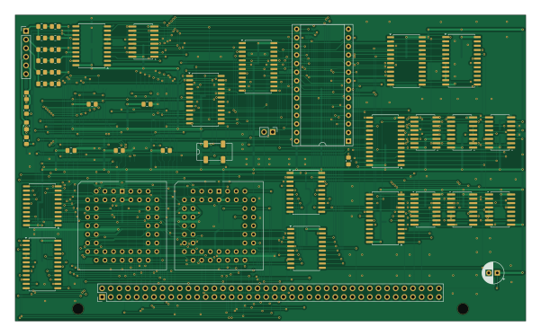
About the HW VGA PCB
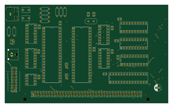
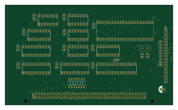
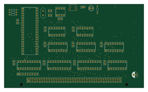
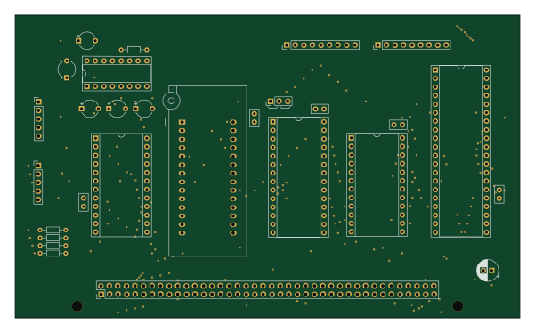
HW VGA is an open source PCB design by daveho, published on GitHub. It is a 2-layer board measuring 150 × 90 mm, with 75 components from 21 distinct parts.
Other key parts include the ATF22V10, 74ALS163, 74ALS157, 74ACT574 and 27SF512. By type, the board carries 28 capacitors, 26 ICs, 17 resistors, 3 connectors and 1 crystal.
From the project
Files and resources for DIY 8 bit computer video series
This directory has a GAL-based VGA text display controller, including a schematic and PCB. Although the design worked as a hand-wired prototype consisting of six boards on a backplane, I wasn't able to get the PCB version (which uses mostly surface mount components) working.
The good news is that an FPGA-based version of the display fully works. The schematic is in the "FPGADisplayController" sheet of the main schematic in the HardwareDesign directory, and the Verilog code is in the FPGADisplayController directory.
Main components on the HW VGA
HW VGA bill of materials (BOM)
75 components, 21 distinct parts.
| Qty | Part | Footprint | Refs |
|---|---|---|---|
| 7 | ATF22V10 | SOIC-24W_7.5x15.4mm_P1.27mm | U102, U202, U301, U601, U605, U707, U803 |
| 9 | 74ALS163 | SOIC-16W_5.3x10.2mm_P1.27mm | U103, U104, U105, U203, U204, U205, U701, U702 +1 |
| 1 | 74ALS157 | SOIC-16W_5.3x10.2mm_P1.27mm | U401 |
| 3 | 74ACT574 | SOIC-20W_7.5x12.8mm_P1.27mm | U403, U602, U604 |
| 1 | 27SF512 | DIP-28_W15.24mm_Socket | U603 |
| 2 | 74ALS273 | SOIC-20W_7.5x12.8mm_P1.27mm | U705, U706 |
| 2 | IDT7134 | PLCC-52_THT-Socket | U801, U802 |
| 1 | 74HCT574 | SOIC-20W_7.5x12.8mm_P1.27mm | U804 |
| 1 | 25.175 MHz | SG-636P | X1 |
| 1 | Conn_02x40_Odd_Even | PinHeader_2x40_P2.54mm_Vertical | J1 |
| 1 | Conn_01x02 | PinHeader_1x02_P2.54mm_Vertical | J301 |
| 1 | Conn_01x06 | PinHeader_1x06_P2.54mm_Vertical | J401 |
| 27 | 100 nF | C_0805_2012Metric_Pad1.18x1.45mm_HandSolder | C1, C102, C103, C104, C105, C202, C203, C204 +19 |
| 1 | 22μF | CP_Radial_D6.3mm_P2.50mm | C6 |
| 3 | 620 | R_0805_2012Metric_Pad1.20x1.40mm_HandSolder | R401, R405, R409 |
| 3 | 75 | R_0805_2012Metric_Pad1.20x1.40mm_HandSolder | R402, R406, R410 |
| 3 | 1K | R_0805_2012Metric_Pad1.20x1.40mm_HandSolder | R403, R407, R411 |
| 3 | 390 | R_0805_2012Metric_Pad1.20x1.40mm_HandSolder | R404, R408, R412 |
| 2 | 2K | R_0805_2012Metric_Pad1.20x1.40mm_HandSolder | R413, R415 |
| 2 | 3K | R_0805_2012Metric_Pad1.20x1.40mm_HandSolder | R414, R416 |
Show 1 more
| Qty | Part | Footprint | Refs |
|---|---|---|---|
| 1 | 4k7 | R_0805_2012Metric_Pad1.20x1.40mm_HandSolder | R601 |
HW VGA design files
The KiCad project lives in the daveho/DIY8bit repository on GitHub; these links point at the commit this page was built from.
HW VGA: common questions
How big is the HW VGA PCB?
The HW VGA measures 150 × 90 mm, has 2 copper layers and is 1.6 mm thick.
How many components are on the HW VGA?
75 components, from 21 distinct parts. The full bill of materials is listed on this page.
Where can I download the HW VGA design files?
From the daveho/DIY8bit repository on GitHub, which has the KiCad layout and the schematic; the links under Design files point to each one.
Can I use the HW VGA design in my own project?
The repository has no license, so all rights stay with daveho. Use it as a reference, and ask the author before reusing the design.