
Solderbit gamepad

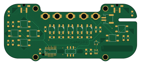
About the Solderbit gamepad PCB
Solderbit gamepad is an open source PCB design by devices-lab, published on GitHub under the GPL-3.0 license. It is a 2-layer board measuring 114 × 49.3 mm, with 42 components from 19 distinct parts.
Other key parts include the 74HC165D,653 and NCP114ASN330T1G. By type, the board carries 10 resistors, 9 switches, 8 capacitors, 6 connectors, 6 diodes and 2 ICs.
From the project
Learn-to-solder kit for the BBC micro:bit
The solder:bit Gamepad is a kit for learning to solder with surface-mount (SMT) components. When assembled, the device functions as a gamepad that connects to a BBC micro:bit. You can then program it as the input controls for any micro:bit project you create!
This soldering kit is designed to accommodate a wide range of soldering abilities, from complete novices to more experienced solderers. To support this, the kit comes in two variants:
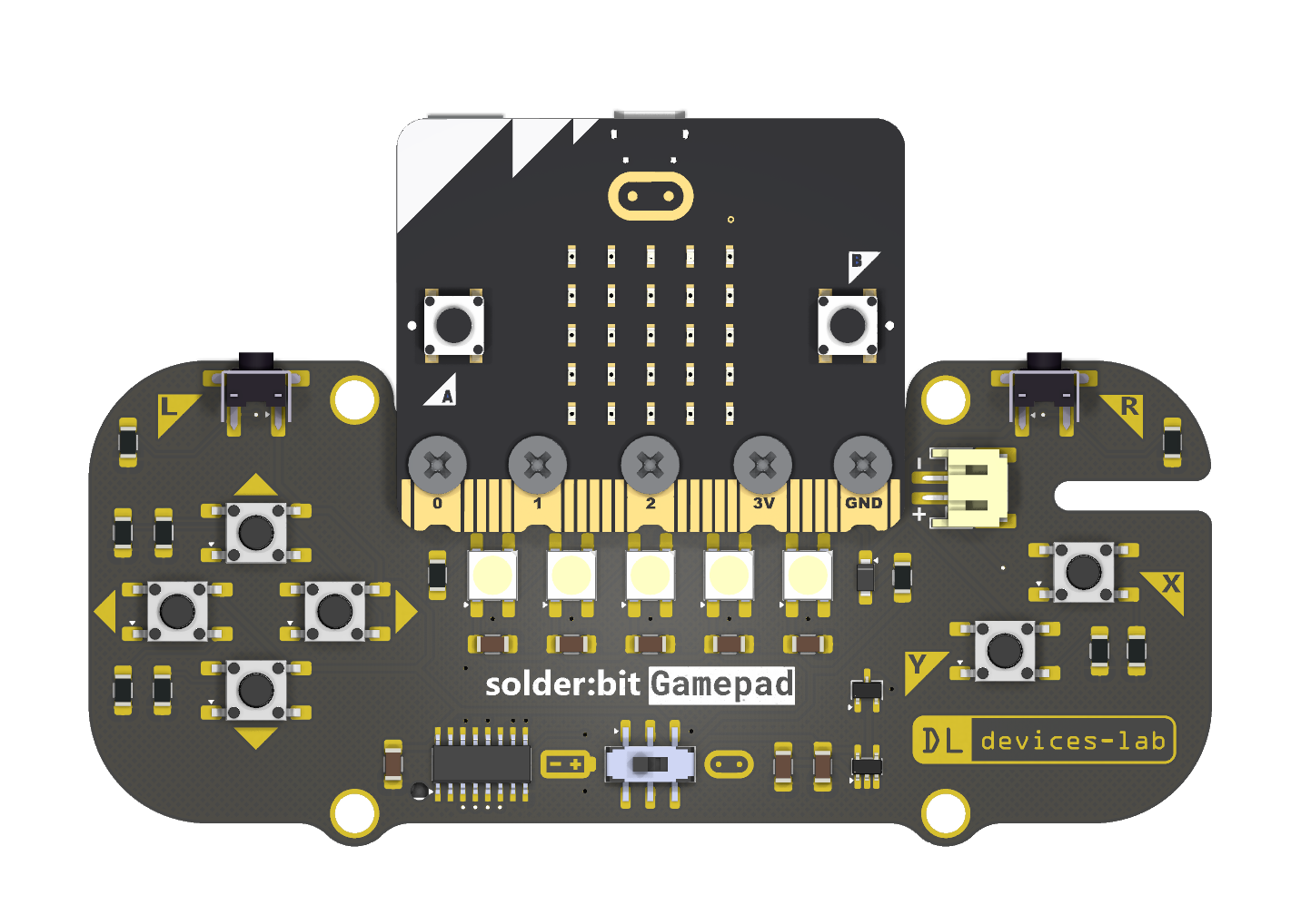
Main components on the Solderbit gamepad
Solderbit gamepad bill of materials (BOM)
42 components, 19 distinct parts — part numbers from the project's BOM.
| Qty | Part | Footprint | Refs |
|---|---|---|---|
| 1 | 74HC165D,653 | Shift_Register_74HC165D | U1 |
| 1 | NCP114ASN330T1G | TSOP-5 | U2 |
| 1 | DMG2045U | TSOT-23 | Q1 |
| 5 | SMTSOM310BTR | SMTSOM310BTR | CN1, CN2, CN3, CN4, CN5 |
| 1 | S2B-PH-SM4-TB(LF)(SN) | JST_PH_S2B-PH-SM4-TB | J2 |
| 1 | KH-6X6X6H-STM XUNPU | Tactile_Switch | S1 |
| 5 | KH-6X6X6H-STM XUNPU | Tactile_Switch | S2, S3, S4, S5, S6 |
| 1 | TS-1037-A4B3-D2 Yuandi | Tactile_Switch_Left_90_Degrees | S7 |
| 1 | TS-1037-A4B3-D2 Yuandi | Tactile_Switch_Right_90_Degrees | S8 |
| 1 | MST22D18G2 125 SHOU HAN | Sliding_Switch_DPDT | SW1 |
| 1 | WS2812B Worldsemi | NeoPixel_WS2812B | D1 |
| 4 | WS2812B Worldsemi | NeoPixel_WS2812B | D2, D3, D4, D5 |
| 1 | MBR120VLSFT1G | SOD-123FL | D6 |
| 4 | 1UF 1uF Samsung Electro-Mechanics | 1206_Capacitor | C1, C2, C7, C8 |
| 4 | 1uF Samsung Electro-Mechanics | 1206_Capacitor | C3, C4, C5, C6 |
| 1 | 100K 100k | 1206_Resistor | R1 |
| 7 | 100k | 1206_Resistor | R2, R3, R4, R5, R6, R7, R8 |
| 1 | 300R | 1206_Resistor | R9 |
| 1 | 3R | 1206_Resistor | R10 |
Solderbit gamepad design files
The KiCad project lives in the devices-lab/solderbit-gamepad repository on GitHub; these links point at the commit this page was built from.
Solderbit gamepad: common questions
How big is the Solderbit gamepad PCB?
The Solderbit gamepad measures 114 × 49.3 mm, has 2 copper layers and is 1.6 mm thick.
How many components are on the Solderbit gamepad?
42 components, from 19 distinct parts, with part numbers taken from the project's own BOM. The full bill of materials is listed on this page.
Where can I download the Solderbit gamepad design files?
From the devices-lab/solderbit-gamepad repository on GitHub, which has the KiCad layout, the schematic and the BOM; the links under Design files point to each one.
Can I use the Solderbit gamepad design in my own project?
Yes, under the terms of its GPL-3.0 license, which devices-lab chose for the repository.
Earlier revisions in the repo: solderbit-gamepad-v0.8, solderbit-gamepad-v0.7, solderbit-gamepad-v0.6, solderbit-gamepad-v0.5, solderbit-gamepad-v0.4, solderbit-gamepad-v0.3, solderbit-gamepad-v0.2, solderbit-gamepad