
Power-Inverter

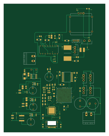
About the Power-Inverter PCB
Power-Inverter is an open source FPGA PCB design by eeden2, published on GitHub. It is a 4-layer board measuring 105 × 132.5 mm, with 99 components from 56 distinct parts.
Its main chip is the XC7S6-1FTGB196I, from the FPGA family. Other key parts include the TL494CN, LM3671MF-1.8/NOPB, FT2232H-56Q-REEL, MT25QL256ABA8ESF-0AAT and LT1111CS8-5#PBF. By type, the board carries 38 capacitors, 33 resistors, 9 ICs, 7 inductors, 6 transistors and 3 connectors.
From the project
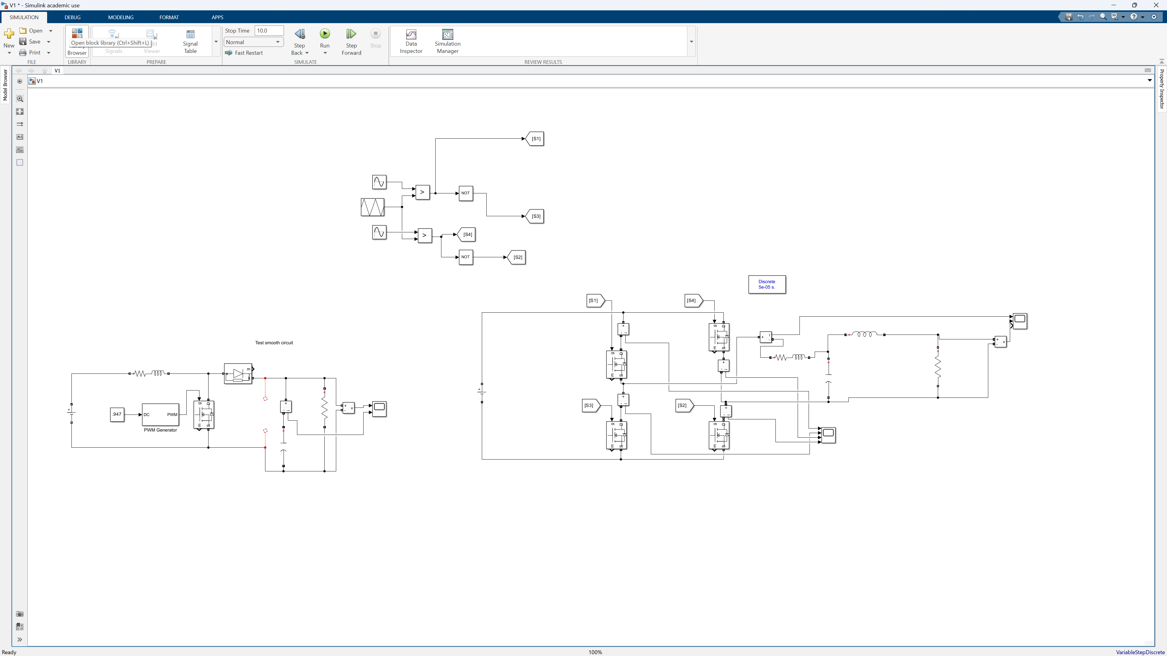
This is a Unipolar Invertion Implementation of a Power Inverter with the help of a PWM via an FPGA.
Main components on the Power-Inverter
Power-Inverter bill of materials (BOM)
99 components, 56 distinct parts.
| Qty | Part | Footprint | Refs |
|---|---|---|---|
| 1 | TL494CN | DIP794W53P254L1930H508Q16N | IC1 |
| 1 | XC7S6-1FTGB196I | BGA196C100P14X14_1500X1500X155 | IC2 |
| 3 | LM3671MF-1.8/NOPB LM3671MF-1.8_NOPB | SOT95P280X145-5N | IC3, IC4, IC5 |
| 1 | FT2232H-56Q-REEL | QFN50P800X800X100-57N-D | IC6 |
| 1 | MT25QL256ABA8ESF-0AAT | SOIC127P1032X265-16N | IC7 |
| 1 | LT1111CS8-5#PBF | SOIC127P599X175-8N | IC9 |
| 1 | KC2520Z | Oscillator_SMD_Kyocera_KC2520Z-4Pin_2.5x2.0mm | U1 |
| 1 | BD139 | TO-126-3_Vertical | Q1 |
| 1 | IRFP250PBF | TO254P465X1024X2050-3P | Q2 |
| 4 | NMOS | TO254P465X1024X2050-3P | Q3, Q4, Q5, Q6 |
| 1 | 12401948E412A | AMPHENOL_12401948E412A | J1 |
| 2 | Conn_01x02_Socket | PhoenixContact_MSTBA_2,5_2-G_1x02_P5.00mm_Horizontal | J2, J3 |
| 1 | PCW1D-C24-KAB104L | PCW1DC24KAB104L | VR1 |
| 1 | 15ETH06 | TO508P465X1031X1932-2P | D1 |
| 1 | MBRS130T3G | DIOM5436X247N | D2 |
| 1 | 220uH | SRR5228A | L1 |
| 2 | 100mH | CAPPRD600W90D1200H2100 | L2, L3 |
| 3 | 2u2 | RCH875NP2R2M | L4, L5, L6 |
| 1 | 68uH | WE-TI_809589 | L7 |
| 3 | 100n | CAPC1608X90N | C1, C34, C41 |
Show 36 more
| Qty | Part | Footprint | Refs |
|---|---|---|---|
| 1 | 2u2 | CAPC2012X140N | C2 |
| 1 | 1n | CAPC2012X94N | C3 |
| 2 | 100p | CAPC1005X55N | C4, C6 |
| 1 | 330u | C0805 | C5 |
| 1 | 10n | CAPC1608X90N | C7 |
| 3 | 47uF | CAPC2012X145N | C8, C16, C17 |
| 8 | 4u7 | CAPC1608X100N | C9, C14, C15, C18, C23, C26, C30, C31 |
| 8 | 0u47 | CAPC3216X152N | C10, C11, C12, C13, C19, C20, C21, C24 |
| 1 | 100uF | CAPPRD350W60D850H1300 | C22 |
| 1 | 1uF | CAPC0603X39N | C25 |
| 1 | 3n5 | C0805 | C27 |
| 1 | 620p | CAPC1608X87N | C28 |
| 3 | 10u | CAPC3225X178N | C29, C33, C35 |
| 1 | 14n | CAPC5750X550N | C32 |
| 1 | 0u1 | CAPC1608X90N | C36 |
| 1 | 47u | CAPC2012X145N | C42 |
| 2 | 47k | RESC1005X37N | R1, R3 |
| 1 | 68k | ERJUP6 | R2 |
| 2 | 22k | ERA8KEB1004V | R4, R5 |
| 5 | 1k | RESC3016X58N | R6, R18, R22, R23, R26 |
| 4 | 12k | ERA8KEB1004V | R7, R31, R32, R33 |
| 1 | 0.1R | RESC15077X100N | R8 |
| 2 | 470R | ERA8KEB1004V | R9, R10 |
| 3 | 10k | RESC1005X37N | R11, R20, R27 |
| 1 | 2k2 | RESC1005X40N | R12 |
| 1 | 27k | ERJUP6 | R13 |
| 1 | 68k | ERJ1GJJ2R4C | R14 |
| 1 | 900 | RESC3116X65N | R15 |
| 1 | 5k6 | ERA2AED122X | R19 |
| 1 | 26k | ERA2AED122X | R21 |
| 1 | 10R | RESC3216X65N | R24 |
| 1 | 22R | RESC3116X65N | R25 |
| 1 | 12k±1% | ERA8KEB1004V | R28 |
| 1 | 4k7 | ERA3AEB101V | R29 |
| 1 | 1k | ERA8KEB1004V | R30 |
| 2 | 5k1 | ERJUP6 | R34, R35 |
Power-Inverter design files
The KiCad project lives in the eeden2/Power-Inverter repository on GitHub; these links point at the commit this page was built from.
- LayoutV1.0/KiCAD/V1.0/V1.0.kicad_pcb
- SchematicV1.0/KiCAD/V1.0/V1.0.kicad_sch
Power-Inverter: common questions
What microcontroller does the Power-Inverter use?
The Power-Inverter is built around the XC7S6-1FTGB196I, from the FPGA family.
How big is the Power-Inverter PCB?
The Power-Inverter measures 105 × 132.5 mm, has 4 copper layers and is 1.6 mm thick.
How many components are on the Power-Inverter?
99 components, from 56 distinct parts. The full bill of materials is listed on this page.
Where can I download the Power-Inverter design files?
From the eeden2/Power-Inverter repository on GitHub, which has the KiCad layout and the schematic; the links under Design files point to each one.
Can I use the Power-Inverter design in my own project?
The repository has no license, so all rights stay with eeden2. Use it as a reference, and ask the author before reusing the design.
Can I test firmware for the Power-Inverter without the hardware?
Yes. HardLabs builds a simulation of the board from its netlist and BOM, so you can run and debug FPGA firmware against it before you order a PCB.
Similar boards
 FPGA
FPGABase board
GlasgowEmbedded
80 × 49 mm222 parts4L0BSD2.2k FPGA
FPGAThunderscope Rev5.3
EEVengers
122.5 × 103.5 mm817 parts6LMIT1.3k FPGA
FPGAUsb sniffer
ataradov
58.2 × 38.1 mm86 parts2LBSD-3-Clause1.3k FPGA
FPGATomu, I'm
theacodes
13 × 9.4 mm40 parts4LMIT1.1k FPGA
FPGAIcepi zero
cheyao
65 × 30 mm143 parts4LSHL-2.1828 FPGA
FPGASd2snes
mrehkopf
101.5 × 83 mm147 partsGPL-2.0717