
EpGB

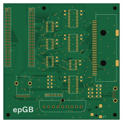
About the EpGB PCB
EpGB is an open source PCB design by ep2k, published on GitHub under the GPL-3.0 license. It is a 2-layer board measuring 100 × 100 mm, with 36 components from 17 distinct parts.
Other key parts include the 74HCT04 and 74LVCC3245. By type, the board carries 13 capacitors, 8 resistors, 7 ICs, 4 connectors and 1 diode.
It belongs with the retro computing designs in this gallery.
From the project
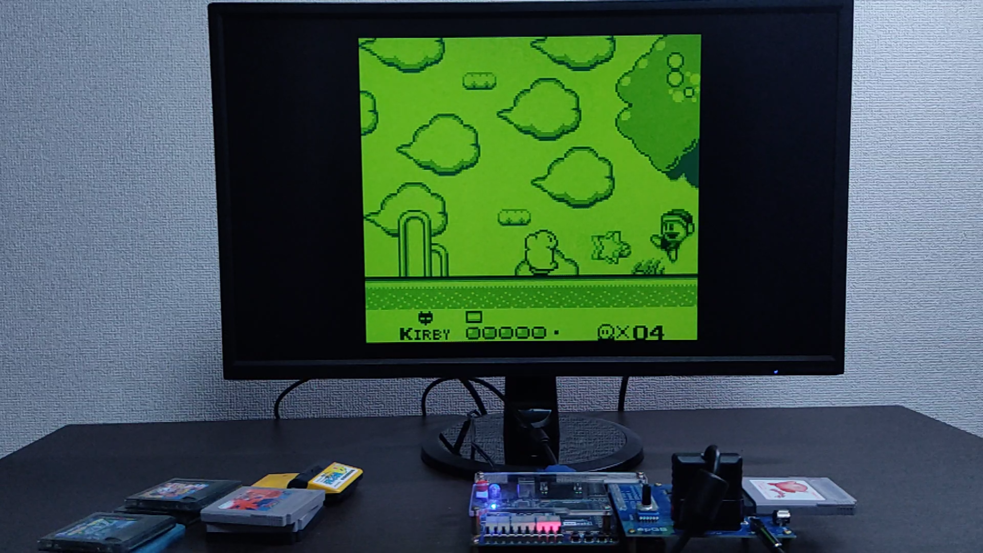
Game Boy / Game Boy Color emulator running on an FPGA
epGB is an implementation of Nintendo's Game Boy (GB) and Game Boy Color (GBC) written in SystemVerilog. It works on an FPGA board with a board for connection to GB/GBC cartridges.
It has no built-in MBCs, and can basically only operate in real-time communication with cartridges.
The system automatically detects whether the cartridge is "for GB", "GB/GBC dual compatible" or "for GBC only" and starts up in GB mode or GBC mode accordingly. In the case of a "GB/GBC dual compatible" cartridge, it is also possible to force startup in GB mode.
Main components on the EpGB
EpGB bill of materials (BOM)
36 components, 17 distinct parts.
| Qty | Part | Footprint | Refs |
|---|---|---|---|
| 4 | 74HCT04 | SOIC-14_3.9x8.7mm_P1.27mm | U1, U2, U3, U4 |
| 3 | 74LVCC3245 | SO-24_5.3x15mm_P1.27mm | U5, U6, U7 |
| 1 | DUALSHOCK | DUALSHOCK_Port | J1 |
| 1 | SJ-3523-SMT-TR | CUI_SJ-3523-SMT-TR | J2 |
| 1 | LinkPort | Game_Boy_Link_Port | J3 |
| 1 | Cartridge | Game_Boy_Card_Edge_Connector | J4 |
| 2 | DE0-CV_GPIO | PinSocket_2x20_P2.54mm_Vertical_Back | GPIO0, GPIO1 |
| 1 | 10k | Potentiometer_Bourns_PTV112 | RV1 |
| 1 | D | D_1206_3216Metric_Pad1.42x1.75mm_HandSolder | D1 |
| 2 | 100p | C_1206_3216Metric_Pad1.33x1.80mm_HandSolder | C1, C2 |
| 1 | 30p | C_1206_3216Metric_Pad1.33x1.80mm_HandSolder | C3 |
| 10 | 0.1u | C_1206_3216Metric_Pad1.33x1.80mm_HandSolder | C4, C5, C6, C7, C8, C9, C10, C11 +2 |
| 2 | 22k | R_1206_3216Metric_Pad1.30x1.75mm_HandSolder | R1, R2 |
| 1 | 2k | R_1206_3216Metric_Pad1.30x1.75mm_HandSolder | R3 |
| 1 | 3.3k | R_1206_3216Metric_Pad1.30x1.75mm_HandSolder | R4 |
| 3 | 220 | R_1206_3216Metric_Pad1.30x1.75mm_HandSolder | R5, R6, R7 |
| 1 | 420 | R_Array_SIP6 | RN1 |
EpGB design files
The KiCad project lives in the ep2k/epGB repository on GitHub; these links point at the commit this page was built from.
EpGB: common questions
How big is the EpGB PCB?
The EpGB measures 100 × 100 mm, has 2 copper layers and is 1.6 mm thick.
How many components are on the EpGB?
36 components, from 17 distinct parts. The full bill of materials is listed on this page.
Where can I download the EpGB design files?
From the ep2k/epGB repository on GitHub, which has the KiCad layout and the schematic; the links under Design files point to each one.
Can I use the EpGB design in my own project?
Yes, under the terms of its GPL-3.0 license, which ep2k chose for the repository.
Similar boards
Expansion Card Retrofit
FrameworkComputer
24 × 27.3 mm5 parts2LCC-BY-4.01.1k
Rgb to hdmi
hoglet67
77 × 97 mm67 parts2LGPL-3.01.0k
Buffer
53.9 × 23.2 mm13 parts2LGPL-3.01.0k
X1
121.9 × 81.3 mm51 parts2LGPL-3.01.0k
Amiga External
21.9 × 76.7 mm6 parts2LGPL-3.01.0k
Videoslotadapter
152 × 57.6 mm13 parts2LGPL-3.01.0k