
BLDC cooler drive v2 - placement

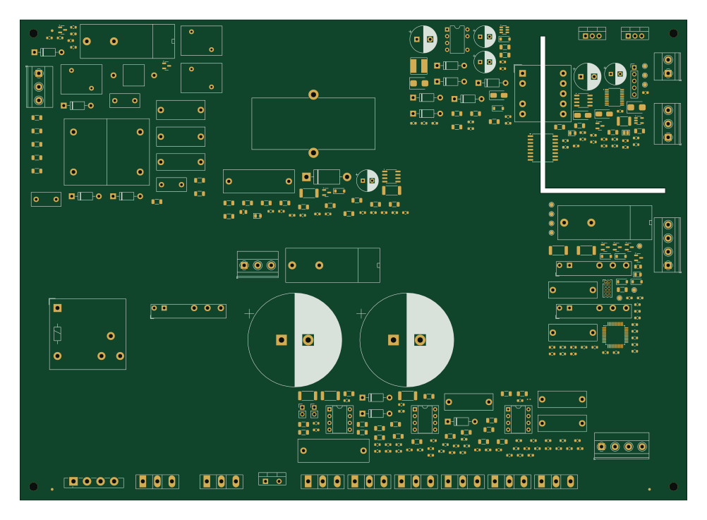
About the BLDC cooler drive v2 - placement PCB
BLDC cooler drive v2 - placement is an open source STM32 PCB design by faragamco-eng, published on GitHub. It is a 2-layer board measuring 250 × 180 mm, with 270 components from 120 distinct parts.
Its main chip is the ST STM32G431CBT6, from the STM32 family. Other key parts include the onsemi NCP1653ADR2G (67 kHz), ST VIPer26LN (60 kHz), Diodes AP63203WU (fixed 3.3 V), Diodes AP2112K-3.3TRG1 and Infineon IRS2186PBF (DIP-8 in socket). By type, the board carries 111 resistors, 67 capacitors, 29 diodes, 14 transistors, 13 ICs and 10 connectors.
It belongs with the robotics & motion designs in this gallery.
From the project
راهنمای کامل (برای هر دو برد، درایو و پنل): docs/10altiumimport.md. خلاصه: مبدل KiCad در Altium باید فعال باشد (Extensions and Updates → Installed → Configure → Importers\Exporters → KiCad)، سپس File → Import Wizard → KiCad Design Files و فایل out/kicad/bldccoolerv2.kicadpro. راه
راهنمای کامل (برای هر دو برد، درایو و پنل): docs/10altiumimport.md. خلاصه: مبدل KiCad در Altium باید فعال باشد (Extensions and Updates → Installed → Configure → Importers\Exporters → KiCad)، سپس File → Import Wizard → KiCad Design Files و فایل out/kicad/bldccoolerv2.kicadpro. راه جایگزین (فقط اتصالات، بدون چیدمان): یک PcbDoc خالی و Design → Import Changes از out/bldccoolerv2altiumprotel.net`.
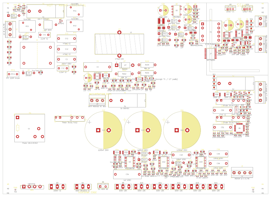
Main components on the BLDC cooler drive v2 - placement
BLDC cooler drive v2 - placement bill of materials (BOM)
270 components, 120 distinct parts — part numbers from the project's BOM.
| Qty | Part | Footprint | Refs |
|---|---|---|---|
| 1 | onsemi NCP1653ADR2G (67 kHz) NCP1653 | SOIC-8_3.9x4.9mm_P1.27mm | U1 |
| 1 | ST VIPer26LN (60 kHz) VIPer26LN | DIP-8-N6_W7.62mm | U2 |
| 1 | Diodes AP63203WU (fixed 3.3 V) AP63203WU | TSOT-23-6 | U3 |
| 1 | Diodes AP2112K-3.3TRG1 AP2112K-3.3 | SOT-23-5 | U4 |
| 3 | Infineon IRS2186PBF (DIP-8 in socket) IRS2186PBF | DIP-8_W7.62mm_Socket | U5, U12, U13 |
| 1 | ST STM32G431CBT6 STM32G431CBT6 | LQFP-48_7x7mm_P0.5mm | U6 |
| 1 | TI ISO7762DWR (reinforced 5 kVrms, SOIC-16 wide) ISO7762DW | SOIC-16W_7.5x10.3mm_P1.27mm | U7 |
| 1 | ST STM32C011F6P6 STM32C011F6P6 | TSSOP-20_4.4x6.5mm_P0.65mm | U8 |
| 1 | LM317T (small heatsink) LM317 CC | TO-220-3_Vertical | U9 |
| 1 | LM317T LM317 REG | TO-220-3_Vertical | U10 |
| 1 | MaxLinear SP3485EN (3.3 V half duplex) SP3485EN | SOIC-8_3.9x4.9mm_P1.27mm | U11 |
| 1 | Infineon IPW65R095C7 / ST STW40N60M6 (heatsink, insulated) 650V 95mOhm SJ | TO-247-3_Vertical | Q1 |
| 6 | 2N7002 | SOT-23 | Q2, Q4, Q5, Q6, Q7, Q8 |
| 1 | ST STW4N150 (on main heatsink, insulated) 1500V 4A | TO-247-3_Vertical | Q3 |
| 6 | ST STW24N60DM2 (fast body diode) / alt. STGW20H60DF IGBT 600V 18A | TO-247-3_Vertical | Q9, Q10, Q11, Q12, Q13, Q14 |
| 1 | Phoenix MKDS 1,5/3-5,08 AC IN L/N/PE | TerminalBlock_Phoenix_MKDS-1,5-3-5.08_1x03_P5.08mm_Horizontal | J1 |
| 1 | MOTOR U/V/W/PE | TerminalBlock_Phoenix_MKDS-1,5-4-5.08_1x04_P5.08mm_Horizontal | J2 |
| 1 | screw-lug NTC 10k B3435 on heatsink NTC 10k B3435 | PinHeader_1x02_P2.54mm_Vertical | J3 |
| 1 | SWD (HOT!) | PinHeader_2x05_P1.27mm_Vertical | J4 |
| 1 | PUMP L/N DRAIN L/N | TerminalBlock_Phoenix_MKDS-1,5-4-5.08_1x04_P5.08mm_Horizontal | J5 |
Show 100 more
| Qty | Part | Footprint | Refs |
|---|---|---|---|
| 1 | SWD SELV | PinHeader_1x05_P2.54mm_Vertical | J6 |
| 1 | PANEL 2-WIRE | TerminalBlock_Phoenix_MKDS-1,5-2-5.08_1x02_P5.08mm_Horizontal | J7 |
| 1 | BATT MODULE RS-485 | TerminalBlock_Phoenix_MKDS-1,5-3-5.08_1x03_P5.08mm_Horizontal | J8 |
| 1 | BATT MODULE DC BUS | TerminalBlock_Phoenix_MKDS-1,5-3-5.08_1x03_P5.08mm_Horizontal | J9 |
| 1 | KSD301 90 C normally closed, on heatsink TSW 90C NC | PinHeader_1x02_P2.54mm_Vertical | J10 |
| 1 | GBU1010 (10 A 1000 V) on heatsink GBU1010 | Diode_Bridge_Vishay_GBU | BR1 |
| 1 | X2 310VAC 470nF X2 | C_Rect_L18.0mm_W7.0mm_P15.00mm_FKS3_FKP3 | CX1 |
| 1 | 470nF X2 | C_Rect_L18.0mm_W7.0mm_P15.00mm_FKS3_FKP3 | CX2 |
| 2 | Y2 300VAC 2.2nF Y2 | C_Disc_D11.0mm_W5.0mm_P7.50mm | CY1, CY2 |
| 1 | 5x20 ceramic 10 A time-lag 10A T 250VAC | Fuseholder_Cylinder-5x20mm_Bulgin_FX0457_Horizontal_Closed | F1 |
| 1 | 5x20 2 A time-lag 2A T | Fuseholder_Cylinder-5x20mm_Bulgin_FX0457_Horizontal_Closed | F2 |
| 1 | Bourns MF-MSMF010 0.1A hold | Fuse_1812_4532Metric | F3 |
| 1 | 5x20 ceramic, DC rated >= 500 V (e.g. Littelfuse 505 series) 5A 500VDC | Fuseholder_Cylinder-5x20mm_Bulgin_FX0457_Horizontal_Closed | F4 |
| 1 | axial 2-electrode GDT 600 V (e.g. Bourns 2026-60 / EPCOS EC600X) GDT 600V | GDT_Axial_P15.24mm | GDT1 |
| 1 | Finder 40.11.9.012.0000 (10 A, 12 V coil) Finder 40.11.9.012 | Relay_SPDT_Finder_40.11 | K1 |
| 3 | Finder 34.51.7.012.0010 Finder 34.51.7.012 | Relay_SPDT_Finder_34.51_Vertical | K2, K3, K4 |
| 1 | inrush PTC rated >= 80 J at 265 VAC (940 uF @ 373 V = 65 J), e.g. TDK/EPCOS J1xx series - verify PTC 120R inrush | C_Disc_D11.0mm_W5.0mm_P7.50mm | PTC1 |
| 1 | EPCOS S14K385 S14K385 | RV_Disc_D15.5mm_W11mm_P7.5mm | RV1 |
| 2 | S14K385 | RV_Disc_D15.5mm_W11mm_P7.5mm | RV2, RV3 |
| 1 | custom, see calc/transformer spec EF20 flyback | Transformer_Myrra_EF20_7408x | T1 |
| 1 | high-efficiency red, 'HIGH VOLTAGE' red HV | LED_0805_2012Metric | LED1 |
| 1 | green | LED_0805_2012Metric | LED2 |
| 1 | yellow | LED_0805_2012Metric | LED3 |
| 3 | 1N4007 | D_DO-41_SOD81_P10.16mm_Horizontal | D1, D2, D3 |
| 2 | BAT54S | SOT-23 | D4, D5 |
| 1 | Wolfspeed C3D08065A / Infineon IDH08G65C6 SiC 650V 8A | TO-220-2_Vertical | D6 |
| 1 | P600M / 1N5408 inrush bypass P600M | D_DO-201AD_P15.24mm_Horizontal | D7 |
| 1 | BZT52C18 | D_SOD-123 | D8 |
| 4 | 1N4764A 1N4764A 100V | D_DO-41_SOD81_P10.16mm_Horizontal | D9, D10, D11, D12 |
| 1 | BZT52C15 | D_SOD-123 | D13 |
| 1 | UF4007 | D_DO-41_SOD81_P10.16mm_Horizontal | D14 |
| 1 | P6KE200CA (bidirectional, 200 V clamp) P6KE200CA | D_DO-41_SOD81_P10.16mm_Horizontal | D15 |
| 2 | ES1D | D_SMA | D16, D20 |
| 5 | 1N4148W | D_SOD-123 | D17, D21, D22, D23, D24 |
| 1 | SMBJ18CA | D_SMB | D18 |
| 1 | SS34 | D_SMA | D19 |
| 1 | SMBJ33CA | D_SMB | D25 |
| 3 | UF4007 (1000 V, 75 ns) UF4007 | D_DO-41_SOD81_P10.16mm_Horizontal | D26, D27, D28 |
| 1 | UF4007 (1000 V) UF4007 | D_DO-41_SOD81_P10.16mm_Horizontal | D29 |
| 1 | ferrite bead 600R@100MHz | L_0603_1608Metric | FB1 |
| 1 | toroidal CM choke 2 x 4.7 mH, >= 10 A (e.g. Schaffner RN series); verify pin map 2x4.7mH 10A | CMC_Toroid_4P_25x15mm | L1 |
| 1 | toroid ~46 mm OD (e.g. Kool Mu 0077083A7 or High Flux 58083), 470 uH at 11 A, Isat >= 13 A 470uH 13A | L_Toroid_Vertical_L46.0mm_W19.1mm_P21.80mm_Bourns_5700 | L2 |
| 1 | Bourns SRN6045TA-6R8M 6.8uH 1A | L_Bourns_SRN6045TA | L3 |
| 4 | 100nF 630V | C_Rect_L18.0mm_W6.0mm_P15.00mm_FKS3_FKP3 | C1, C35, C36, C40 |
| 5 | 1NF 1nF | C_0603_1608Metric | C2, C3, C7, C8, C41 |
| 2 | 1uF 630V | C_Rect_L26.5mm_W8.5mm_P22.50mm_MKS4 | C4, C34 |
| 1 | 22uF 25V | CP_Radial_D8.0mm_P3.50mm | C5 |
| 21 | 100NF 100nF | C_0603_1608Metric | C6, C17, C20, C27, C29, C31, C33, C42 +13 |
| 1 | 100PF 100pF | C_0603_1608Metric | C9 |
| 1 | 220PF 220pF | C_0603_1608Metric | C10 |
| 1 | 1UF 1uF | C_0805_2012Metric | C11 |
| 2 | 470 uF 450 V 105 C >= 5000 h snap-in D35 (e.g. Nichicon LGN/LGU, TDK B43544, Rubycon USR) 470uF 450V | CP_Radial_D35.0mm_P10.00mm_SnapIn | C12, C13 |
| 1 | 10uF 450V | CP_Radial_D10.0mm_P5.00mm | C14 |
| 1 | 220uF 35V | CP_Radial_D8.0mm_P3.50mm | C15 |
| 1 | 10uF 35V | CP_Radial_D8.0mm_P3.50mm | C16 |
| 1 | 2.2NF 2.2nF | C_0603_1608Metric | C18 |
| 5 | 10uF 25V | C_1206_3216Metric | C19, C26, C63, C65, C67 |
| 1 | 22uF 10V | C_1206_3216Metric | C21 |
| 4 | 1UF 1uF | C_0603_1608Metric | C22, C24, C47, C55 |
| 1 | 220uF 16V | CP_Radial_D8.0mm_P3.50mm | C23 |
| 1 | 470uF 50V | CP_Radial_D10.0mm_P5.00mm | C25 |
| 3 | 4.7uF 25V X7R | C_1206_3216Metric | C28, C30, C32 |
| 3 | 470pF C0G | C_0603_1608Metric | C37, C38, C39 |
| 1 | 4.7UF 4.7uF | C_0805_2012Metric | C46 |
| 2 | 47nF X2 | C_Rect_L18.0mm_W6.0mm_P15.00mm_FKS3_FKP3 | C50, C51 |
| 1 | 1uF 50V | C_1206_3216Metric | C57 |
| 1 | 10uF 35V | C_1206_3216Metric | C58 |
| 2 | 10NF 10nF | C_0603_1608Metric | C59, C69 |
| 2 | 470K 470k | R_1206_3216Metric | R1, R2 |
| 14 | 1M | R_1206_3216Metric | R3, R4, R5, R7, R8, R9, R22, R23 +6 |
| 5 | 10k 0.1% | R_0603_1608Metric | R6, R10, R60, R61, R62 |
| 7 | 1k | R_0603_1608Metric | R11, R12, R53, R70, R73, R88, R96 |
| 2 | 10R | R_0603_1608Metric | R13, R17 |
| 15 | 10K 10k | R_0603_1608Metric | R14, R41, R43, R45, R47, R49, R51, R52 +7 |
| 2 | 50m 3W | R_2512_6332Metric | R15, R16 |
| 4 | 470k 1% | R_1206_3216Metric | R18, R19, R20, R21 |
| 1 | 4.7K 4.7k | R_0603_1608Metric | R26 |
| 1 | 22K 22k | R_0603_1608Metric | R27 |
| 6 | 100K 100k | R_0603_1608Metric | R28, R76, R79, R82, R85, R94 |
| 3 | 100K 100k | R_1206_3216Metric | R29, R30, R31 |
| 1 | 36k 1% | R_0603_1608Metric | R36 |
| 3 | 10k 1% | R_0603_1608Metric | R37, R71, R98 |
| 1 | 2.2K 2.2k | R_0603_1608Metric | R38 |
| 1 | DNP | R_0603_1608Metric | R39 |
| 11 | 100R | R_0603_1608Metric | R40, R42, R44, R46, R48, R50, R75, R78 +3 |
| 3 | 25m 2W | R_2512_6332Metric | R54, R55, R56 |
| 3 | 1k 0.1% | R_0603_1608Metric | R57, R58, R59 |
| 3 | 330k 1% | R_1206_3216Metric | R66, R67, R68 |
| 1 | 6.65k 0.1% | R_0603_1608Metric | R69 |
| 1 | 68R 0.5W | R_1206_3216Metric | R74 |
| 3 | 220R | R_0603_1608Metric | R77, R80, R83 |
| 2 | 100R 1W | R_2512_6332Metric | R86, R87 |
| 1 | 8.2R 0.5W | R_1206_3216Metric | R89 |
| 1 | 240R 1% | R_0603_1608Metric | R90 |
| 1 | 4.3k 1% | R_0603_1608Metric | R91 |
| 1 | 8.2k 1% | R_0603_1608Metric | R92 |
| 1 | 4.7R 1% | R_1206_3216Metric | R95 |
| 1 | 100k 1% | R_0603_1608Metric | R97 |
| 1 | 120R | R_0603_1608Metric | R99 |
| 9 | 10R | R_1206_3216Metric | R107, R109, R111, R113, R115, R117, R119, R120 +1 |
BLDC cooler drive v2 - placement design files
The KiCad project lives in the faragamco-eng/Multiact repository on GitHub; these links point at the commit this page was built from.
BLDC cooler drive v2 - placement: common questions
What microcontroller does the BLDC cooler drive v2 - placement use?
The BLDC cooler drive v2 - placement is built around the ST STM32G431CBT6, from the STM32 family.
How big is the BLDC cooler drive v2 - placement PCB?
The BLDC cooler drive v2 - placement measures 250 × 180 mm, has 2 copper layers and is 1.6 mm thick.
How many components are on the BLDC cooler drive v2 - placement?
270 components, from 120 distinct parts, with part numbers taken from the project's own BOM. The full bill of materials is listed on this page.
Where can I download the BLDC cooler drive v2 - placement design files?
From the faragamco-eng/Multiact repository on GitHub, which has the KiCad layout, the schematic and the BOM; the links under Design files point to each one.
Can I use the BLDC cooler drive v2 - placement design in my own project?
The repository has no license, so all rights stay with faragamco-eng. Use it as a reference, and ask the author before reusing the design.
Can I test firmware for the BLDC cooler drive v2 - placement without the hardware?
Yes. HardLabs builds a simulation of the board from its netlist and BOM, so you can run and debug STM32 firmware against it before you order a PCB.
More boards in Multiact
Similar boards
 STM32
LumenPnP Motherboard
opulo-inc
149 × 95 mm296 parts4LCC-BY-SA-4.03.7k STM32
Type g
google
169 × 30 mm24 parts2LApache-2.02.9k STM32
Main panel
234 × 84 mm26 parts4LApache-2.02.9k STM32
Base
52.3 × 52.3 mm36 parts2LApache-2.02.9k STM32
Type a
150 × 30 mm14 parts2LApache-2.02.9k STM32
Type c
188 × 30 mm17 parts2LApache-2.02.9k