${PCB NAME}

About the ${PCB NAME}
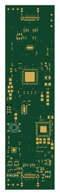
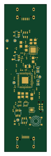
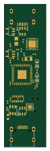
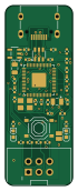
${PCB NAME} is an open source PCB design by fcjr, published on GitHub under the Apache-2.0 license. It is a 2-layer board measuring 16 × 43 mm, with 35 components from 20 distinct parts.
Other key parts include the RP2354A and RT9013-33GB. By type, the board carries 14 capacitors, 11 resistors, 3 diodes, 2 ICs, 2 connectors and 1 crystal.
From the project
Reformat an Apple Silicon mac from any platform.
SWD probe for flashing dongle-lite and dongle-pro boards over their TC2030 pads. The TC2030-IDC-NL cable plugs straight into J2, no adapter wiring.
RP2354A + USB-C, runs the stock debugprobe firmware built for Pico 2 (DEBUGONPICO=ON): GP2 = SWCLK, GP3 = SWDIO, GP25 = activity LED. Hold BOOT while plugging in and drop the UF2 on the mass storage device.
J2 is a shrouded 2.54 mm 2x3 box header; the TC2030-IDC-NL cable ends in a 6-pin 0.1" IDC socket whose polarizing bump only fits the key notch one way. It's wired 1:1 with the target TC2030 pads:
Main components on the ${PCB NAME}
${PCB NAME} bill of materials (BOM)
35 components, 20 distinct parts — part numbers from the project's BOM.
| Qty | Part | Footprint | Refs |
|---|---|---|---|
| 1 | RP2354A Raspberry Pi | QFN-60_L7.0-W7.0-P0.40-TL-EP3.4 | U1 |
| 1 | RT9013-33GB Richtek | SOT-23-5_L3.0-W1.7-P0.95-LS2.8-BL | U2 |
| 1 | X322512MSB4SI YXC | CRYSTAL-SMD_4P-L3.2-W2.5-BL | Y1 |
| 1 | TYPE-C-31-M-12 Korean Hroparts Elec | USB-C_SMD-TYPE-C-31-M-12_1 | J1 |
| 1 | 2.54-2*3P BOOMELE | PinHeader_2x03_P1.27mm_Vertical | J2 |
| 1 | TS-1187A-B-A-B XKB Connection | SW-SMD_4P-L5.1-W5.1-P3.70-LS6.5-TL_H1.5 | SW1 |
| 2 | KT-0603R KENTO | LED-SMD_L1.6-W0.8-R-RD | D1, D2 |
| 1 | USBLC6-2SC6 STMicroelectronics | SOT-23-6_L2.9-W1.6-P0.95-LS2.8-BL | D3 |
| 1 | AOTA-B201610S3R3-101-T Abracon | IND-SMD_L2.0-W1.6_AOTA-B201610S3R3-101-T | L1 |
| 1 | GRM21BZ71E106KE15K Murata Electronics | C_0805_2012Metric | C1 |
| 2 | GRM155Z71A105KE01D Murata Electronics | C_0402_1005Metric | C2, C8 |
| 1 | 4.7uF | C_0402_1005Metric | C3 |
| 1 | 1UF 4.7uF | C_0402_1005Metric | C4 |
| 1 | 100NF 4.7uF | C_0402_1005Metric | C5 |
| 2 | GCM1555C1H220FA16D Murata Electronics | C_0402_1005Metric | C6, C7 |
| 6 | GCM155R71H104KE02D Murata Electronics | C_0402_1005Metric | C9, C10, C11, C12, C13, C14 |
| 2 | ERJ-2RKF5101X Panasonic Electronic Components | R_0402_1005Metric | R1, R2 |
| 5 | ERJ-2RKF33R0X Panasonic Electronic Components | R_0402_1005Metric | R3, R6, R7, R8, R11 |
| 1 | 0402WGF5101TCE ERJ-2RKF5101X UNI-ROYAL | R_0402_1005Metric | R4 |
| 3 | ERJ-2RKF1001X Panasonic Electronic Components | R_0402_1005Metric | R5, R9, R10 |
${PCB NAME} design files
The KiCad project lives in the fcjr/restorekit repository on GitHub; these links point at the commit this page was built from.
${PCB NAME}: common questions
How big is the ${PCB NAME}?
The ${PCB NAME} measures 16 × 43 mm, has 2 copper layers and is 1.62 mm thick.
How many components are on the ${PCB NAME}?
35 components, from 20 distinct parts, with part numbers taken from the project's own BOM. The full bill of materials is listed on this page.
Where can I download the ${PCB NAME} design files?
From the fcjr/restorekit repository on GitHub, which has the KiCad layout and the BOM; the links under Design files point to each one.
Can I use the ${PCB NAME} design in my own project?
Yes, under the terms of its Apache-2.0 license, which fcjr chose for the repository.