
Circuit tap

About the Circuit tap PCB
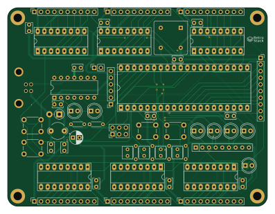
Circuit tap is an open source AVR/Arduino PCB design by gcoonrod, published on GitHub under the Apache-2.0 license. It is a 4-layer board measuring 99.1 × 75.7 mm, with 58 components from 34 distinct parts.
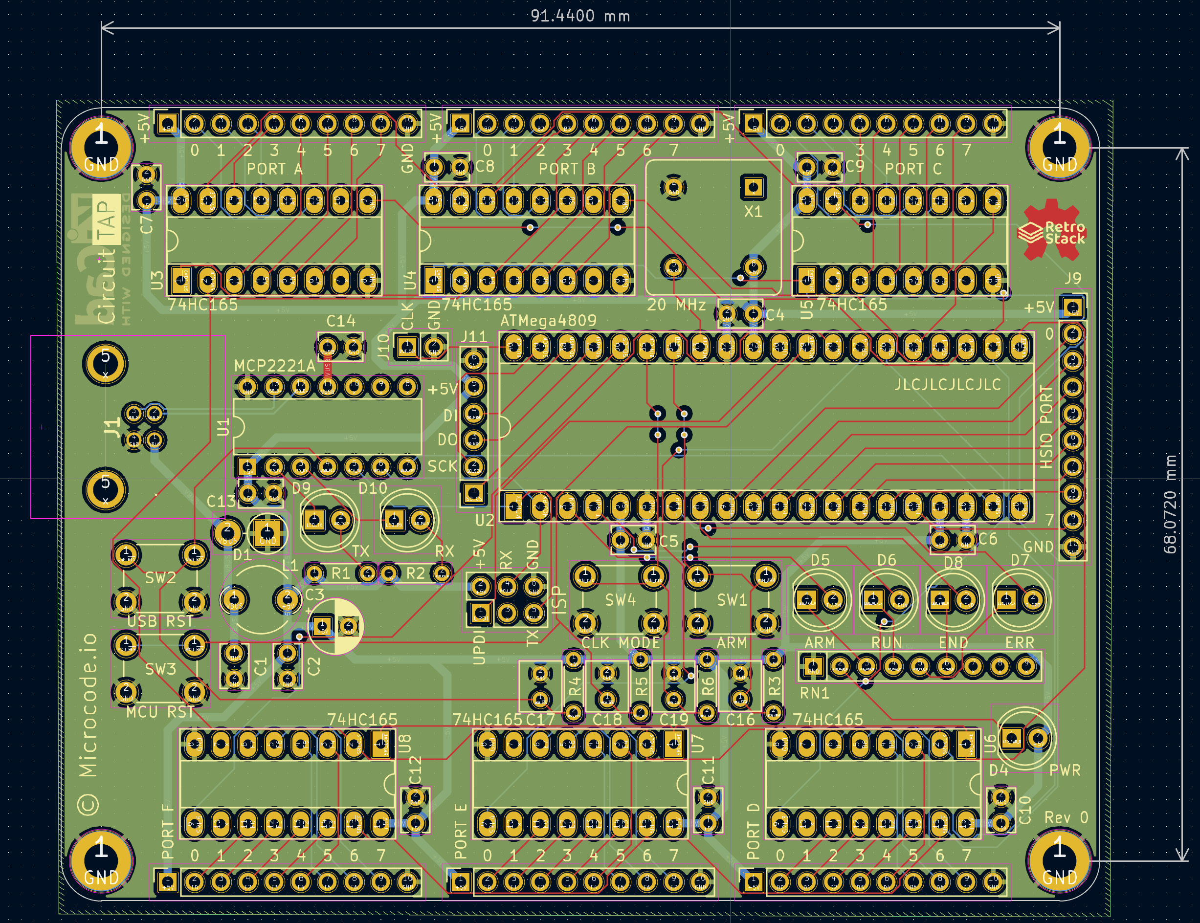
Its main chip is the ATMEGA4809-PF, from the AVR/Arduino family. Other key parts include the MCP2221A-I/P and CD74HC165E. By type, the board carries 18 capacitors, 11 connectors, 8 ICs, 8 diodes, 7 resistors and 4 switches.
It belongs with the retro computing designs in this gallery.
From the project
A low-speed digital logic analyzer designed around 74HC165 shift registers and the ATMega4809 MCU.
A low-speed digital logic analyzer designed around 74HC165 shift registers and the ATMega4809 MCU.
The Circuit Tap is designed to serve as a digital logic analyzer for primarily low speed circuits (<= 1Mhz). It is intended to aid in debugging the RetroStack, a 6502 based hobbyist computer. As I do not (at the time of designing this tool) own an oscilliscope or logic analyzer, I needed a way to monitor the address bus, data bus, and numerous control signals of the RetroStack while the clock was freely running. For very simple programs it was sufficient to use a manually stepped clock to…
Main components on the Circuit tap
Circuit tap bill of materials (BOM)
58 components, 34 distinct parts.
| Qty | Part | Footprint | Refs |
|---|---|---|---|
| 1 | MCP2221A-I/P Microchip | DIP-14_W7.62mm | U1 |
| 1 | ATMEGA4809-PF Microchip | DIP-40_W15.24mm_Socket_LongPads | U2 |
| 6 | CD74HC165E Texas Instruments | DIP-16_W7.62mm_Socket_LongPads | U3, U4, U5, U6, U7, U8 |
| 1 | ACH-20.000MHZ-EK ABRACON | Oscillator_DIP-8 | X1 |
| 1 | UJ2-BH-1-TH CUI Devices | UJ2BH1TH | J1 |
| 1 | HDR_UPDI Amphenol | PinHeader_2x03_P2.54mm_Vertical | J2 |
| 1 | HDR_PORTA Wurth Elektronik | PinSocket_1x10_P2.54mm_Vertical | J3 |
| 1 | HDR_PORTB Wurth Elektronik | PinSocket_1x10_P2.54mm_Vertical | J4 |
| 1 | HDR_PORTC Wurth Elektronik | PinSocket_1x10_P2.54mm_Vertical | J5 |
| 1 | HDR_PORTD Wurth Elektronik | PinSocket_1x10_P2.54mm_Vertical | J6 |
| 1 | HDR_PORTE Wurth Elektronik | PinSocket_1x10_P2.54mm_Vertical | J7 |
| 1 | HDR_PORTF Wurth Elektronik | PinSocket_1x10_P2.54mm_Vertical | J8 |
| 1 | HDR_HSIO Wurth Elektronik | PinSocket_1x10_P2.54mm_Vertical | J9 |
| 1 | HDR_DUT_CLK Preci-dip | PinSocket_1x02_P2.54mm_Vertical | J10 |
| 1 | HDR_SD Wurth Elektronik | PinSocket_1x06_P2.54mm_Vertical | J11 |
| 1 | SW_ARM CUI Devices | SW_PUSH_6mm | SW1 |
| 1 | SW_USB_RST TE Connectivity / P&B | SW_PUSH_6mm | SW2 |
| 1 | SW_MCU_RST TE Connectivity / P&B | SW_PUSH_6mm | SW3 |
| 1 | SW_CLK CUI Devices | SW_PUSH_6mm | SW4 |
| 1 | P6KE-AT YAGEO | D_DO-15_P3.81mm_Vertical_AnodeUp | D1 |
Show 14 more
| Qty | Part | Footprint | Refs |
|---|---|---|---|
| 1 | LED_PWR Kingbright | LED_D5.0mm | D4 |
| 1 | LED_ARM Kingbright | LED_D5.0mm | D5 |
| 1 | LED_RUN Kingbright | LED_D5.0mm | D6 |
| 1 | LED_ERR Kingbright | LED_D5.0mm | D7 |
| 1 | LED_END Kingbright | LED_D5.0mm | D8 |
| 1 | LED_TX Kingbright | LED_D5.0mm | D9 |
| 1 | LED_RX Kingbright | LED_D5.0mm | D10 |
| 1 | 600R Laird Performance Materials | LairdTech_28C0236-0JW-10 | L1 |
| 1 | 10n Vishay | C_Rect_L4.0mm_W2.5mm_P2.50mm | C1 |
| 12 | 100n Vishay | C_Rect_L4.0mm_W2.5mm_P2.50mm | C2, C4, C5, C6, C7, C8, C9, C10 +4 |
| 1 | 4u7 Panasonic | CP_Radial_D5.0mm_P2.50mm | C3 |
| 4 | 1u TDK | C_Rect_L4.6mm_W3.8mm_P2.50mm_MKS02_FKP02 | C16, C17, C18, C19 |
| 6 | 1k Vishay | R_Axial_DIN0204_L3.6mm_D1.6mm_P5.08mm_Horizontal | R1, R2, R3, R4, R5, R6 |
| 1 | 1k Bourns | R_Array_SIP9 | RN1 |
Circuit tap design files
The KiCad project lives in the gcoonrod/circuit-tap repository on GitHub; these links point at the commit this page was built from.
- Layoutcircuit-tap.kicad_pcb
- Schematiccircuit-tap.kicad_sch
Circuit tap: common questions
What microcontroller does the Circuit tap use?
The Circuit tap is built around the ATMEGA4809-PF, from the AVR/Arduino family.
How big is the Circuit tap PCB?
The Circuit tap measures 99.1 × 75.7 mm, has 4 copper layers and is 1.6062 mm thick.
How many components are on the Circuit tap?
58 components, from 34 distinct parts. The full bill of materials is listed on this page.
Where can I download the Circuit tap design files?
From the gcoonrod/circuit-tap repository on GitHub, which has the KiCad layout and the schematic; the links under Design files point to each one.
Can I use the Circuit tap design in my own project?
Yes, under the terms of its Apache-2.0 license, which gcoonrod chose for the repository.
Can I test firmware for the Circuit tap without the hardware?
Yes. HardLabs builds a simulation of the board from its netlist and BOM, so you can run and debug AVR/Arduino firmware against it before you order a PCB.
Similar boards
 AVR/Arduino
Magspoof
samyk
35 × 29 mm11 parts2LNo license4.2k AVR/Arduino
Redox keyboard
mattdibi
162.2 × 126.5 mm77 parts2LMIT2.0k AVR/Arduino
Labrador
espotek-org
36.8 × 34.7 mm75 parts2LNo license1.2k AVR/Arduino
V4
stuartpittaway
30 × 50 mm38 parts2LCC-BY-NC-4.01.1k AVR/Arduino
ModuleV450
30 × 61.4 mm39 parts2LCC-BY-NC-4.01.1k AVR/Arduino
Discipline
coseyfannitutti
304.9 × 122.8 mm170 parts2LCC-BY-NC-4.01.0k