
RTB C02

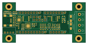
About the RTB C02 PCB
RTB C02 is an open source AVR/Arduino PCB design by git4dcc, published on GitHub under the Apache-2.0 license. It is a 4-layer board measuring 75.7 × 36.8 mm, with 81 components from 44 distinct parts.
Its main chip is the ATMEGA328PB-MU, from the AVR/Arduino family. Other key parts include the NME0505SC, MIC5235-5.0, LM393, FT230XQ and ISO7742. By type, the board carries 30 resistors, 18 capacitors, 16 diodes, 8 connectors, 7 ICs and 1 crystal.
From the project
DCC Railcom real-time logger to debug downstream/upstream protocol traffic.
My C02 module is designed to trace DCC Railcom traffic for decoder debugging and development purposes. In particular the Railcom capture is an important feature and helps to validate if a decoders is RCN-217 compliant. The C02 uses the Vt100 terminal emulation control codes for its user interface. Therefore a VT100 capeable terminal program is a must (e.g. putty, teraterm). The USB interface is galvanically isolated from the DCC track potential.
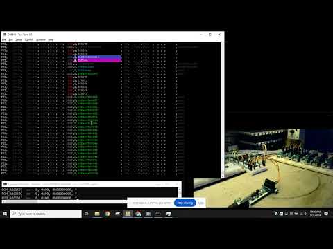
Main components on the RTB C02
RTB C02 bill of materials (BOM)
81 components, 44 distinct parts — part numbers from the project's BOM.
| Qty | Part | Footprint | Refs |
|---|---|---|---|
| 1 | ATMEGA328PB-MU ATmega328PB-MU | QFN-32-1EP_5x5mm_P0.5mm_EP3.1x3.1mm | U1 |
| 1 | NME0505SC | DCDC-Conv_muRata_NMAxxxxSC | U2 |
| 1 | MIC5235-5.0 | SOT-23-5 | U3 |
| 1 | LM393 | DFN-8_2x2mm_P0.5mm | U4 |
| 1 | FT230XQ | QFN-16-1EP_4x4mm_P0.65mm_EP2.5x2.5mm | U6 |
| 1 | ISO7742 | SSOP-16_3.9x4.9mm_P0.635mm | U7 |
| 1 | ISO7740 | SSOP-16_3.9x4.9mm_P0.635mm | U8 |
| 1 | C1986052 16Mhz, 6pF | Crystal_SMD_2016-4Pin_2.0x1.6mm | Y1 |
| 1 | C2688795 USB_B_Mini | USB_Micro-B_Reichelt_BWM_SMD | J1 |
| 1 | CONN_01X10_MALE Conn_01x10_Male | PinHeader_1x10_P2.54mm_Vertical | J2 |
| 1 | CONN_01X06_MALE Conn_01x06_Male | PinHeader_1x06_P2.54mm_Vertical | J3 |
| 2 | CONN_01X08_MALE Conn_01x08_Male | PinHeader_1x08_P2.54mm_Vertical | J4, J5 |
| 1 | SCREW_TERMINAL_01X04 Screw_Terminal_01x04 | TerminalBlock_RND_205-00003_1x04_P5.00mm_Horizontal | J6 |
| 1 | ISP | PinHeader_2x03_P2.54mm_Vertical | J11 |
| 1 | CONN_01X02 Conn_01x02 | PinHeader_1x02_P2.54mm_Vertical | J12 |
| 1 | D_Schottky | D_0603_1608Metric | D1 |
| 1 | C143804 D_Schottky | D_0603_1608Metric | D2 |
| 2 | BAT54S | SOT-323_SC-70 | D3, D4 |
| 1 | BAT54A | SOT-323_SC-70 | D5 |
| 3 | C2289 LED_grn | LED_0603_1608Metric | D8, D11, D12 |
Show 24 more
| Qty | Part | Footprint | Refs |
|---|---|---|---|
| 2 | SSA33L | D_SMA | D10, D19 |
| 1 | C2289 Hbt(grn) | LED_0603_1608Metric | D13 |
| 1 | C2287 INF(ylw) | LED_0603_1608Metric | D14 |
| 1 | C2288 ACK(blu) | LED_0603_1608Metric | D15 |
| 1 | C2289 LED(grn) | LED_0603_1608Metric | D16 |
| 2 | C125099 LED_red | LED_0603_1608Metric | D17, D18 |
| 1 | C1017 Ferrite_Bead | L_0805_2012Metric | L1 |
| 7 | 1u | C_0603_1608Metric | C1, C9, C10, C16, C17, C18, C19 |
| 3 | 10U/25V 10u/25V | C_0603_1608Metric | C2, C6, C8 |
| 4 | 100N 100n | C_0603_1608Metric | C5, C7, C11, C22 |
| 2 | 8p | C_0402_1005Metric | C12, C13 |
| 2 | 47P 47p | C_0603_1608Metric | C14, C15 |
| 1 | 220 | R_0805_2012Metric | R1 |
| 4 | 1k | R_0603_1608Metric | R4, R5, R6, R8 |
| 4 | 100K 100k | R_0603_1608Metric | R7, R10, R12, R33 |
| 2 | 33K 33k | R_0603_1608Metric | R9, R11 |
| 1 | 220K 220k | R_0603_1608Metric | R13 |
| 2 | 10K 10k | R_0603_1608Metric | R14, R32 |
| 10 | 4.7K 4.7k | R_0603_1608Metric | R15, R22, R23, R24, R25, R26, R28, R29 +2 |
| 2 | 27 | R_0603_1608Metric | R16, R20 |
| 1 | 3.3K 3.3k | R_0603_1608Metric | R19 |
| 1 | 10 | R_0603_1608Metric | R21 |
| 1 | 0 | R_0603_1608Metric | R27 |
| 1 | 4.7K 4.7k | R_Array_Concave_4x0603 | RN1 |
RTB C02 design files
The KiCad project lives in the git4dcc/RTB_C02 repository on GitHub; these links point at the commit this page was built from.
- LayoutC02.kicad_pcb
- SchematicC02.kicad_sch
- BOMproduction/bom.csv
RTB C02: common questions
What microcontroller does the RTB C02 use?
The RTB C02 is built around the ATMEGA328PB-MU, from the AVR/Arduino family.
How big is the RTB C02 PCB?
The RTB C02 measures 75.7 × 36.8 mm, has 4 copper layers and is 1.6 mm thick.
How many components are on the RTB C02?
81 components, from 44 distinct parts, with part numbers taken from the project's own BOM. The full bill of materials is listed on this page.
Where can I download the RTB C02 design files?
From the git4dcc/RTB_C02 repository on GitHub, which has the KiCad layout, the schematic and the BOM; the links under Design files point to each one.
Can I use the RTB C02 design in my own project?
Yes, under the terms of its Apache-2.0 license, which git4dcc chose for the repository.
Can I test firmware for the RTB C02 without the hardware?
Yes. HardLabs builds a simulation of the board from its netlist and BOM, so you can run and debug AVR/Arduino firmware against it before you order a PCB.
Similar boards
 AVR/Arduino
V4
stuartpittaway
30 × 50 mm38 parts2LCC-BY-NC-4.01.1k AVR/Arduino
ModuleV450
30 × 61.4 mm39 parts2LCC-BY-NC-4.01.1k AVR/Arduino
Easyduino Atmega
Hanqaqa
68.8 × 53.6 mm35 parts4LCERN-OHL-P-2.0746 AVR/Arduino
Easyduino Atmega Nano
43.4 × 18 mm30 parts4LCERN-OHL-P-2.0746 AVR/Arduino
UsbGpib
xyphro
54 × 15 mm21 parts2LMIT683 AVR/Arduino
Lumberjack
peej
284.7 × 94.2 mm149 parts2LMIT402